Pneumatic tire and process for its manufacture

a technology of pneumatic tires and longitudinal grooves, which is applied in the field of pneumatic tires, can solve the problems of lower actual draining capacity of longitudinal grooves during pneumatic tire rolling, and achieve the effect of reducing the global rigidity of tread bands and optimizing tire performan

Active Publication Date: 2007-08-16
PIRELLI TYRE SPA
View PDF2 Cites 22 Cited by
  • Summary
  • Abstract
  • Description
  • Claims
  • Application Information

AI Technical Summary

Benefits of technology

[0042] In this way, it is advantageously possible to achieve a reduction of the global rigidity of the tread band (with respect to the previous situation or to the situation in which the aforementioned layer is absent), both along the longitudinal and the transversal directions, adapted to optimize the performances of the tire such as the driving behavior.
[0043] Preferably, the layer interposed between the tread band and the belt structure has a thickness comprised between 1 and 5 mm so as to be able to fully achieve the aforementioned technical effects.
[0044] In a preferred embodiment, the width of the aforementioned at least one first radial sector is at least equal to the width of the longitudinal groove formed therein. In such a way, it is advantageously possible to achieve the technical effect of keeping unchanged the cross section of the groove when the tread band gets in touch with the ground.
[0045] Preferably, the difference between the width of said at least one first radial sector and the width of said at least one longitudinal groove is comprised between 4 and 10 mm. In such a way, it is advantageously possible to have, on both sides of the groove, a more than adequate quantity of the first elastomeric material to avoid undesired deformations of the side walls of the grooves under the ground contacting area of the pneumatic tire when the tread band gets in touch with the ground.

Problems solved by technology

In known pneumatic tires, however, the actual draining capacity of these longitudinal grooves during the pneumatic tire rolling is lower than the theoretical capacity expected on the basis of the geometrical configuration of the grooves.

Method used


Image

  • Pneumatic tire and process for its manufacture
  • Pneumatic tire and process for its manufacture
  • Pneumatic tire and process for its manufacture

Examples


example

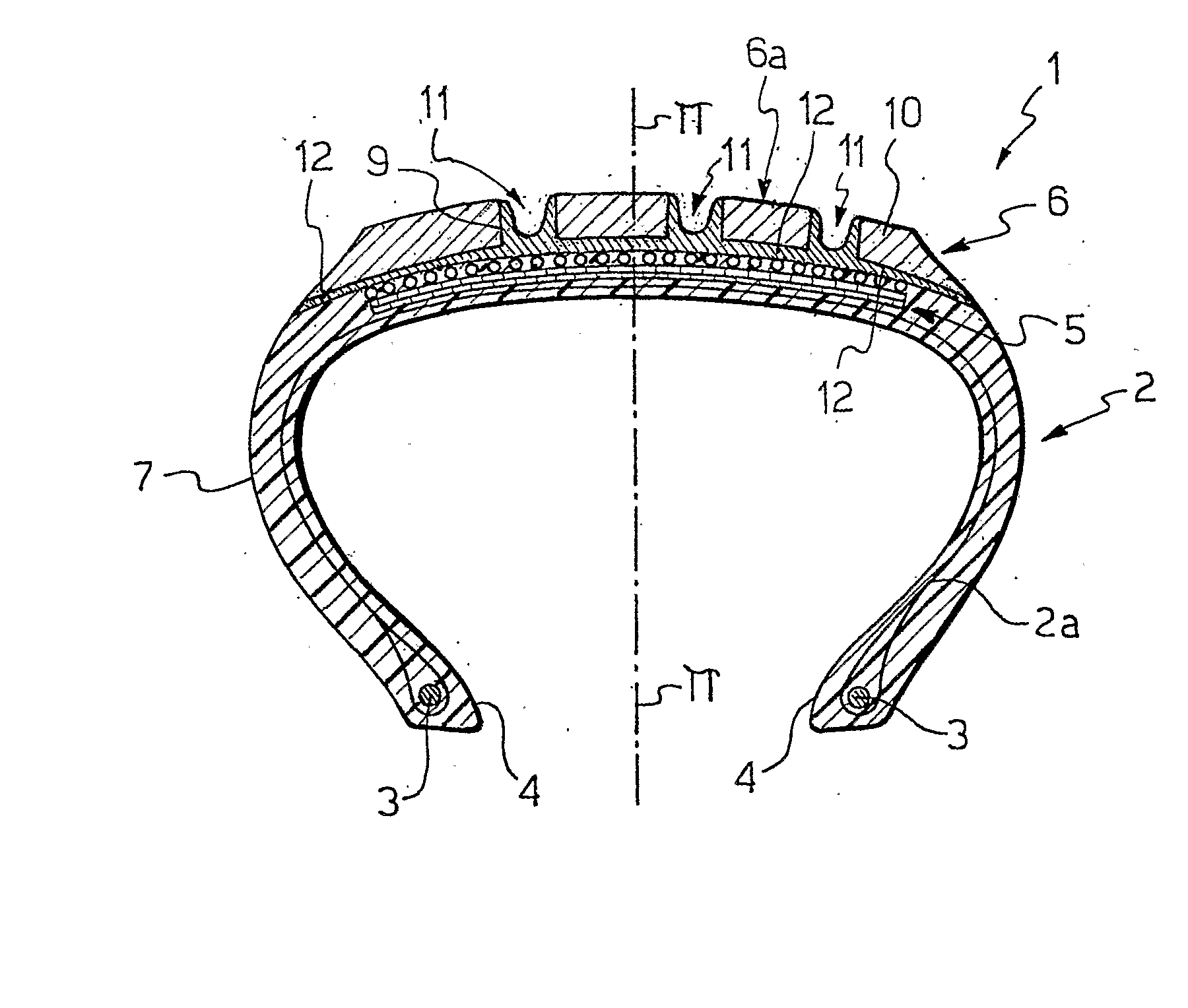
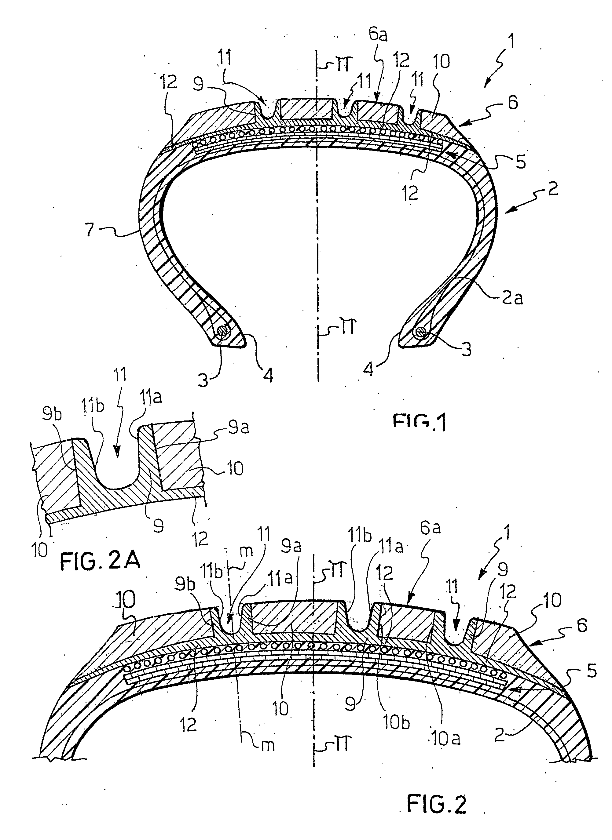
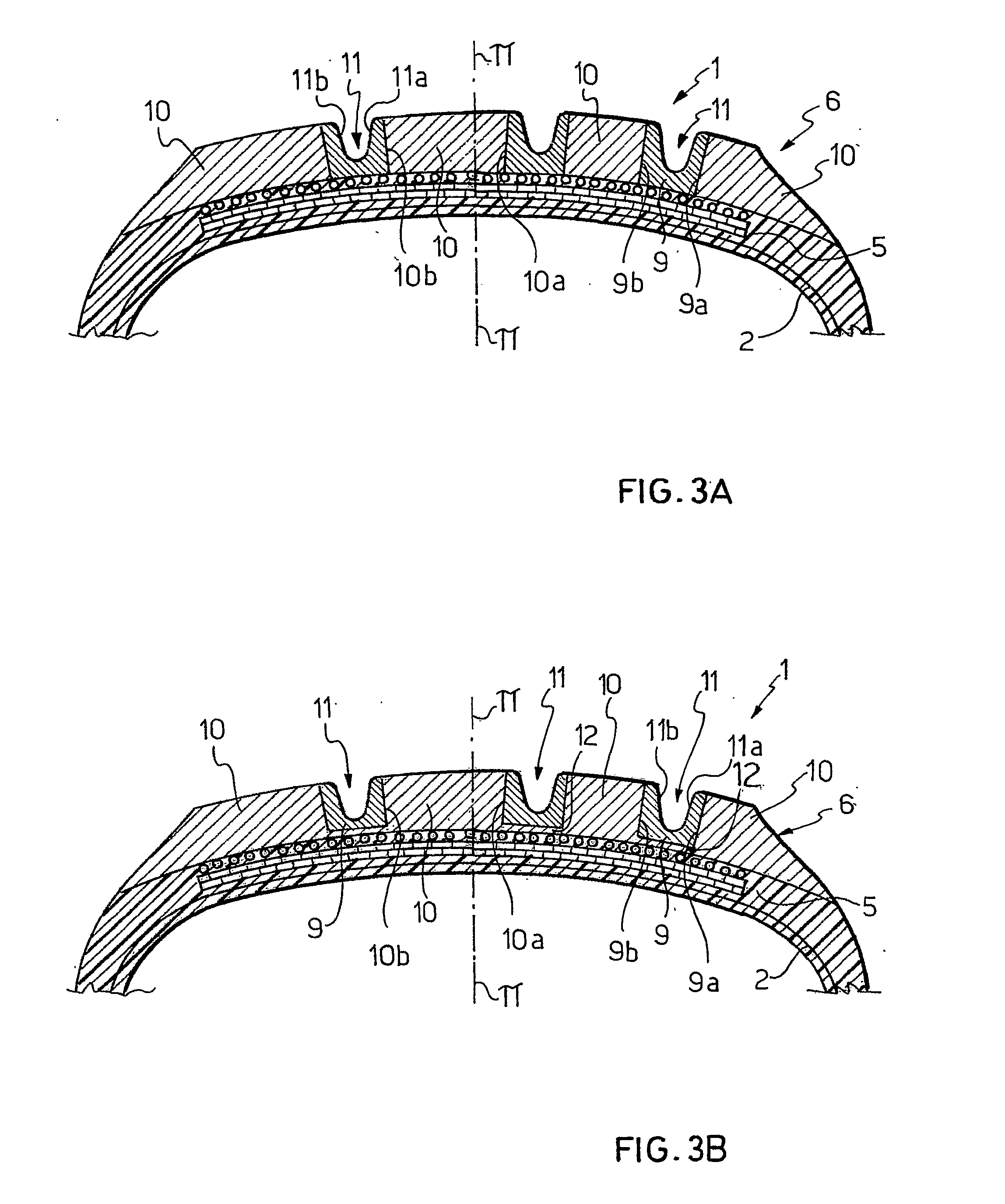
[0101] Elastomeric materials have been prepared, designated with A and B in the following Table 1, which can be used for making the first and second sectors 9, 10 according to the present invention of the tread band 6. In Table 1, all of the amounts are expressed in phr.

TABLE 1material Amaterial BIngredients(first sectors 9)(second sectors 10)E-SBR 17126070E-SBR 1500—30NR SMR2040—carbon black N2346030SiO23535SiO2 binding agent67aromatic oil510stearic acid1.51.5ZnO2.52.56PPD22DPG11TBBS—1.5CBS2.0—soluble sulfur4.51.3

[0102] The ingredients used were the following: [0103] E-SBR 1712=butadiene-styrene copolymer prepared in emulsion commercially available with the trade name of KRYNOL®1712 (BAYER); [0104] E-SBR 1500=butadiene-styrene copolymer prepared in emulsion commercially available with the trade name of KRYLENE®1500 (BAYER); [0105] NR SMR20=natural rubber; [0106] carbon black N234=a product available on the market with the trade name of VULCAN®7H (CABOT CORPORATION); [0107] SiO2=s...


PUM

PropertyMeasurementUnit
thicknessaaaaaaaaaa
widthaaaaaaaaaa
temperatureaaaaaaaaaa

Abstract

A pneumatic tire has a carcass structure having at least one carcass ply and at least one annual reinforcing structure associated with the carcass ply, a tread band made of an elastomeric material at a radially outer position with respect to the carcass structure, a belt structure interposed between the carcass structure and the tread band and a pair of axially opposite side walls on the carcass structure, wherein the tread band has i) at least one first sector, radially extending, substantially of a first elastomeric material; ii) a plurality of second sectors radially extending, positioned at axially opposite sides of the at least one first sector and substantially of a second elastomeric material; iii) at least one longitudinal groove formed in the at least one first sector and extending substantially for the entire circumferential development of the tread band, wherein the first elastomeric material has a modulus of elasticity under compression at 23° C. greater than the modulus of elasticity under compression at 23° C. of the second elastomeric material, and wherein the modulus of elasticity under compression at 23° C. of the first elastomeric material is about 20 to about 80 MPa.

Description

BACKGROUND OF THE INVENTION [0001] The present invention refers to a pneumatic tire for two-wheeled or four-wheeled vehicles and in particular, but not exclusively, to a pneumatic tire for motorvehicles. [0002] Specifically, the present invention refers to a pneumatic tire comprising a carcass structure having at least one carcass ply, and at least one annular reinforcing structure associated to the carcass ply, a tread band made of an elastomeric material at a radially outer position with respect to the carcass structure, a belt structure interposed between the carcass structure and the tread band and a pair of axially opposite sidewalls on the carcass structure, wherein the tread band is of the type comprising a plurality of radially extending and axially adjacent sectors. PRIOR ART [0003] In the field of pneumatic tires for vehicles one of the most felt needs is that of ensuring a suitable drainage of water or mud present under the ground contacting area of the pneumatic tire on ...

Claims


Application Information

Patent Timeline
Patent Type & Authority Applications(United States)
IPC IPC(8): B29D30/08B60C11/00B60C11/04B60C11/18
CPCB60C11/0306B60C11/18B60C11/005B60C11/0058B60C2011/0025B60C11/1346
Inventor LOSI, PIERODE CANCELLIS, PIERLUIGILO PRESTI, GAETANONOTO, RODOLFOLACAGNINA, CLAUDIO
Owner PIRELLI TYRE SPA
Why Eureka
Try Eureka