Heat exchanger

a technology of heat exchanger and heat exchanger plate, which is applied in the direction of machines/engines, lighting and heating apparatus, laminated elements, etc., can solve the problems of leaking cooling water, failure of brazing in the brazed portion, failure of brazing, etc., and achieves good brazing performance and small processing steps.

Inactive Publication Date: 2007-08-16
DENSO CORP
View PDF8 Cites 5 Cited by
  • Summary
  • Abstract
  • Description
  • Claims
  • Application Information

AI Technical Summary

Benefits of technology

[0009]In view of above problems, it is an object of the present invention to provide a heat exchanger that is capable of being manufactured in small number of processing steps and exhibiting a good brazing performance.
[0011]In accordance with the first aspect, the portion of a tube to be inserted into an insertion hole of the core plate may be formed to have generally the same shape as the periphery of the insertion hole so that brazing performance of the core plate and the tube can be improved. Also, in accordance with the first aspect, the portions of the first and the second tube plates to be inserted into the insertion hole of the core plate have overlapping sections that overlap each other in the tube laminating direction. Therefore, by using a jig or the like to compress the overlapping sections in the tube laminating direction, the overlapping sections can be securely abutted to each other and brazing performance can be thereby improved.
[0012]In accordance with the second aspect, the overlapping sections (104c, 104d) are formed by attaching inner surfaces of the first tube plate (104a) and the second tube plate (104b) to each other. Therefore, in accordance with the second aspect, the tube plates can be formed in a shape that permits easy molding.
[0013]In accordance with the third aspect, the overlapping sections (104c, 104d) are fixed in calking by bending one of the first tube plate (104a) and the second tube plate (104b). By fixing the overlapping sections in the shape of joined hands in calking, the overlapping sections can be more securely fixed and brazing performance can be further improved.
[0014]In accordance with the fourth aspect, said overlapping sections are formed outside of said tube, with the end section of the tube in the longitudinal direction of said overlapping section abutted to said core plate. In accordance with the fourth aspect, as the end section of the tube in the longitudinal direction of the overlapping section is abutted to the core plate, positioning in the longitudinal direction of the tube relative to the core plate can be accomplished without requiring any jig.

Problems solved by technology

In mounting the inner fins inside the tubes, in one method, the inner fins are slid and inserted into the tubes, so that mutual contact may peel off brazing material and cause a defect in a brazed portion, leading to leakage of cooling water.
As a result, there is a problem that a gap may be formed at the fitting section 201f and may cause a brazing failure in the brazed portion.
Also, there is a problem that, as shown in FIG. 16, a step 201g is produced as a result of forming the fitting section 201f, and this step increases the clearance between the tube 201 and the opening edge of the tube insertion hole 202 through which the tube 201 is inserted, leading to brazing failure.
Further, when a heat exchanger of larger size is used, it is very difficult to achieve sufficient positioning accuracy of individual components, and therefore, it is required to use a jig or the like for adjustment, leading to another problem of increasing the number of processing steps.

Method used


Image

  • Heat exchanger
  • Heat exchanger
  • Heat exchanger

Examples


Embodiment Construction

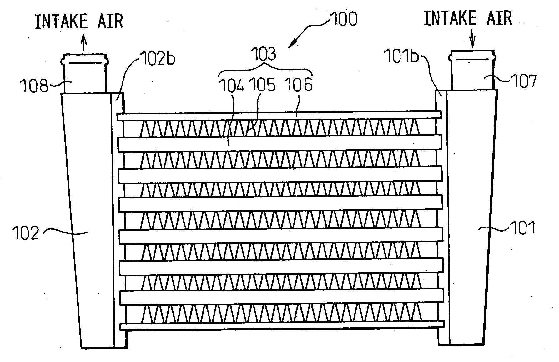
[0033]Now, the present invention will be described in detail with reference to appended drawings showing embodiments thereof. A heat exchanger according to the present invention is suitable to be applied to an apparatus for cooling intake air used in a supercharger of an internal combustion engine. FIG. 1 is a front view showing a heat exchanger 100 according to the present invention. The heat exchanger 100 comprises a pair of tanks 101, 102 and a heat exchanging core section 103 for heat exchange between the supercharged air and external air, brazed in one unit.

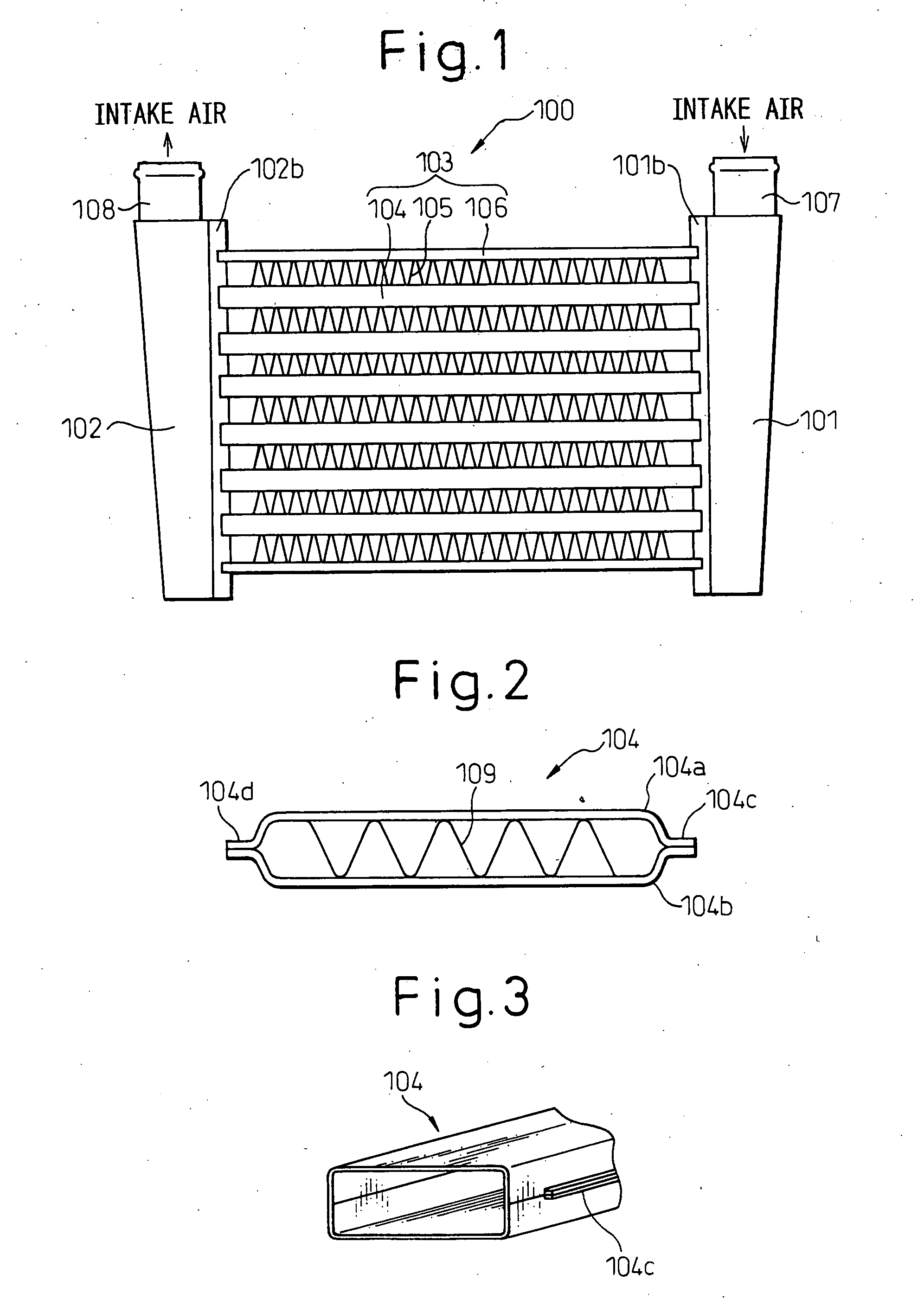
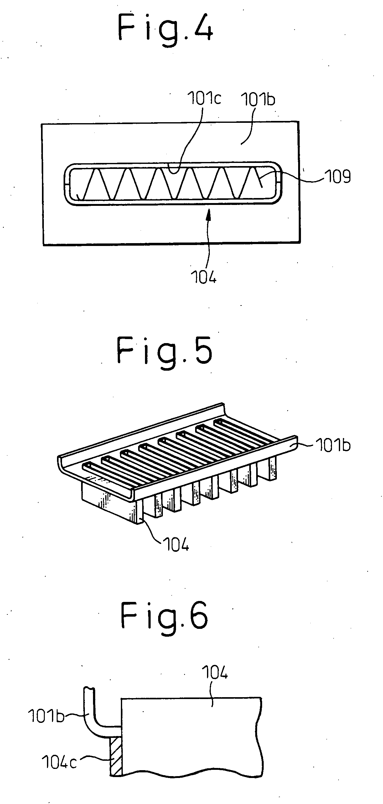
[0034]The tanks 101, 102 are composed of tank bodies 101a, 102a and core plates 101b, 102b, respectively. The core plates 101b, 102b have tube insertion holes 101c, 102c formed therein for inserting tubes 104. An inlet pipe 107 is connected to the upper end portion of the tank 101 as an inlet for supercharged air. An outlet pipe 108 is connected to the upper end portion of the tank 102 as an outlet for supercharged air.

[0035...


PUM


Abstract

A heat exchanger comprising: a plurality of tubes inside of which a fluid passes; fins which are joined to the outer surfaces of the tubes and promote heat exchange between a fluid passing around the tubes and the fluid passing through inside the tube; and tank sections comprising core plates having insertion holes formed for the tubes to be inserted therein and tank bodies having the core plates joined thereto for distributing or collecting the fluid to be passed through the tubes; the tube comprises a first and a second tube plates joined in opposition to each other and inner fins disposed between the first and second tube plates, and that the portion of the tube to be inserted into the insertion hole of the core plate has generally the same outer shape as the periphery of the insertion hole, and that the portions of the first and second tube plates not to be inserted into the insertion hole of the core plate have overlapping sections which overlap each other in laminating direction of the tubes.

Description

BACKGROUND OF THE INVENTION[0001]1. Field of the Invention[0002]The present invention relates to a heat exchanger and, more particularly, to a heat exchanger for a supercharger in an internal combustion engine.[0003]2. Description of Related Art[0004]Conventionally, a heat exchanger for a supercharger in an internal combustion engine used for cooling thermally-expanded intake air in order to increase charging efficiency of the intake air has been known, for example from Japanese Patent Publication No. 2002-286394, which discloses a heat exchanger having a pair of tanks, a plurality of tubes through which super-charged air passes, and fins for increasing heat discharge, brazed together in one unit. In such a heat exchanger, the tank comprises a tank body and a core plate, and the tubes are inserted through insertion holes formed in the core plate.[0005]In such a heat exchanger, in order to further increase heat exchange efficiency, inner fins are provided inside the tubes. In mountin...

Claims


Application Information

Patent Timeline
Patent Type & Authority Applications(United States)
IPC IPC(8): F28F9/02
CPCF28D1/0316F28D1/0391F28D2021/0082F28F1/04F28F9/0263F28F3/025F28F9/18Y02T10/146F02B29/0456F28F1/126Y02T10/12
Inventor WATANABE, HARUHIKOSUSA, SUMIOHARADA, MASAKI
Owner DENSO CORP
Why Eureka
Try Eureka