Refill container
- Summary
- Abstract
- Description
- Claims
- Application Information
AI Technical Summary
Benefits of technology
Problems solved by technology
Method used
Image

Examples
first embodiment
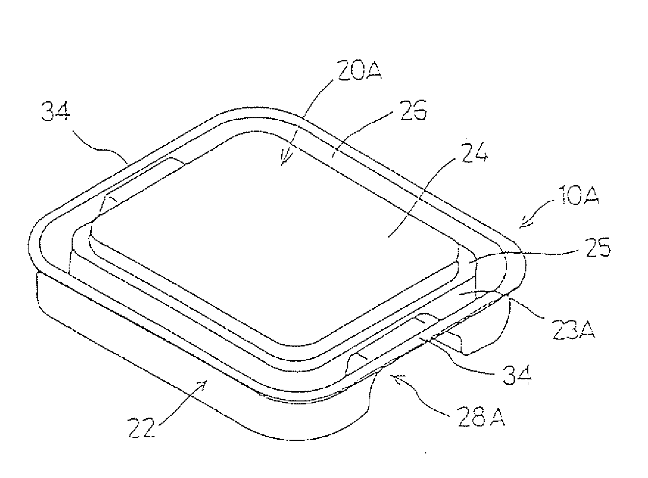
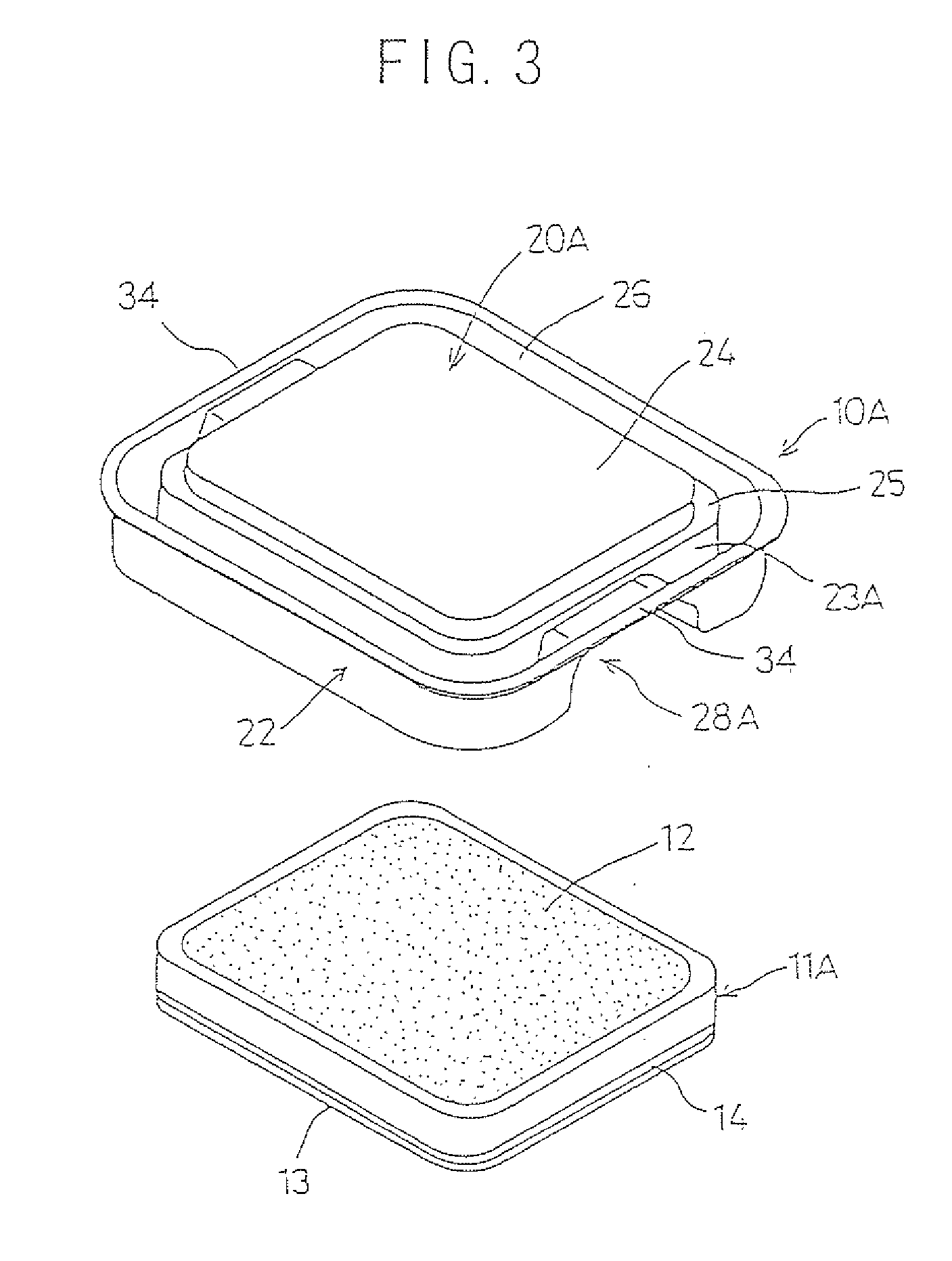
[0058]FIGS. 3 through 7 show a refill container 10A according to the present invention. The refill container 10A holds and protects an internal tray 11A whose inside is filled with a cosmetic material 12. In this embodiment, the cosmetic material 12 is illustrated as one using a powdery cosmetic material, for example, a foundation, etc.
[0059] The refill container 10A is made of plastic material by integral molding, using, for example, a vacuum forming technique or an injection molding technique, etc. As for a material, recycled amorphous polyethylene terephthalate (APET) is employed in this embodiment. The recycled amorphous polyethylene terephthalate (APET) is less costly than brand new plastics (i.e., plastics other than recycled materials). Therefore, the cost of the refill container 10A can be reduced by employing the recycled APET. It also provides the capability to address environmental issues, more specifically, recycling promotion and waste reduction, etc.
[0060] This embodi...
second embodiment
[0079] Next, the present invention is described.
[0080]FIGS. 8 through 11 show a refill container 10B of the second embodiment. It should be noted that those configurations in FIGS. 8 through 11 that are the same as the aforementioned ones of the refill container 10A of the first embodiment described with reference to the FIGS. 3 and 7 are indicated by the same reference numerals and description for them is omitted. Later in the description, the same thing applies to the third through sixth embodiments and FIGS. 12 through 27, which are used for describing the third through sixth embodiments.
[0081] The refill container 10A of the first embodiment is particularly configured to prevent the external force from being applied directly onto the internal tray 11A from the side portion by the provision of the turn-back portion 22. However, the configuration that provides the turn-back portion 22 at the outside of the mounting portion 20A is still quite large relative to the contour of the i...
third embodiment
[0089] Next, the present invention is described.
[0090]FIG. 12 shows a refill container 10C of the third embodiment. The refill container 10A of the aforementioned first embodiment is configured in such a manner that the internal tray 11A is held within the mounting portion 20A by the engagement of the engaging portion 21A with the catching groove 14 formed at the side surface of the internal tray 11A.
[0091] In contrast, the refill container 10C of this embodiment is characterized in that an engaging portion 31 is engaged with the internal-tray bottom surface 13 of the internal tray 11B. The engaging portion 31 is formed in the shape of a rib and is configured to be capable of being flexibly deformed to allow insertion of the internal tray 11B when the internal tray 11B is inserted and mounted in the holding portion 23C. Further, it is configured to elastically return to the original shape and engage with the internal-tray bottom surface 13 of the internal tray 11B when the internal...
PUM
| Property | Measurement | Unit |
|---|---|---|
| Size | aaaaa | aaaaa |
| Level | aaaaa | aaaaa |
Abstract
Description
Claims
Application Information
 - R&D
- Intellectual Property
- Life Sciences
- Materials
- Tech Scout
- Unparalleled Data Quality
- Higher Quality Content
- 60% Fewer Hallucinations
Browse by: Latest US Patents, China's latest patents, Technical Efficacy Thesaurus, Application Domain, Technology Topic, Popular Technical Reports.
© 2025 PatSnap. All rights reserved.Legal|Privacy policy|Modern Slavery Act Transparency Statement|Sitemap|About US| Contact US: help@patsnap.com