Access panel for a wind turbine tower and method for securing same

Active Publication Date: 2018-02-01
VESTAS WIND SYST AS
View PDF2 Cites 6 Cited by
  • Summary
  • Abstract
  • Description
  • Claims
  • Application Information

AI Technical Summary

Benefits of technology

[0031]The size of an access panel can vary although in larger turbines, these may extend in a height dimension up to around six or eight metres or more with a width of up to two metres or more. As such, these panels, being large and therefore also heavy can pose a challenge to put in place or to remove when required. Weather considerations may also need to be taken into account such as winds, which can preclude or at least seriously complicate application (closure) or removal (opening) operations. As such, the need both to support and to accurately locate an access panel such as shown in DE102008035350 or in WO2009094991, at its corresponding tower aperture is difficult and in some conditions, impossible. In offshore locations, the operation may be more difficult still. In order to facilitate insertion and correct seating of the access panel in a tower wall aperture, the access panel may optionally comprise a main panel and a separate sub-panel, the main- and sub-panels being configured for separate positioning into or removal from a said tower aperture. In this w

Problems solved by technology

The need to provide access into a tower 2 for personnel can pose a problem in relation to the structural properties of the tower wall.
In large turbines, especially larger land-based turbines and offshore turbines, some components located in the tower can be very large and bulky, and sometimes extremely heavy: of the order of several tonnes or tens of tonnes.
The provision of holes in the tower wall proves detrimental to its structural strength, in particular in the case of steel tower walls.
Also, significant welds around a steel tower wall aperture can considerably weaken a tower.
Both welds or holes may in particular generate significant local stress concentrations which may precipitate structural failure under conditions in which a plain wall without these features would maintain its integr

Method used


Image

  • Access panel for a wind turbine tower and method for securing same
  • Access panel for a wind turbine tower and method for securing same
  • Access panel for a wind turbine tower and method for securing same

Examples


Embodiment Construction

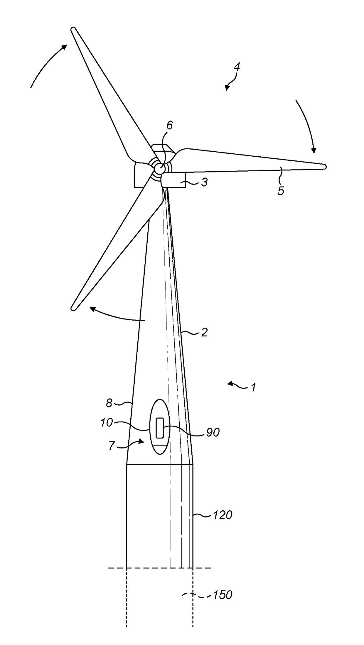
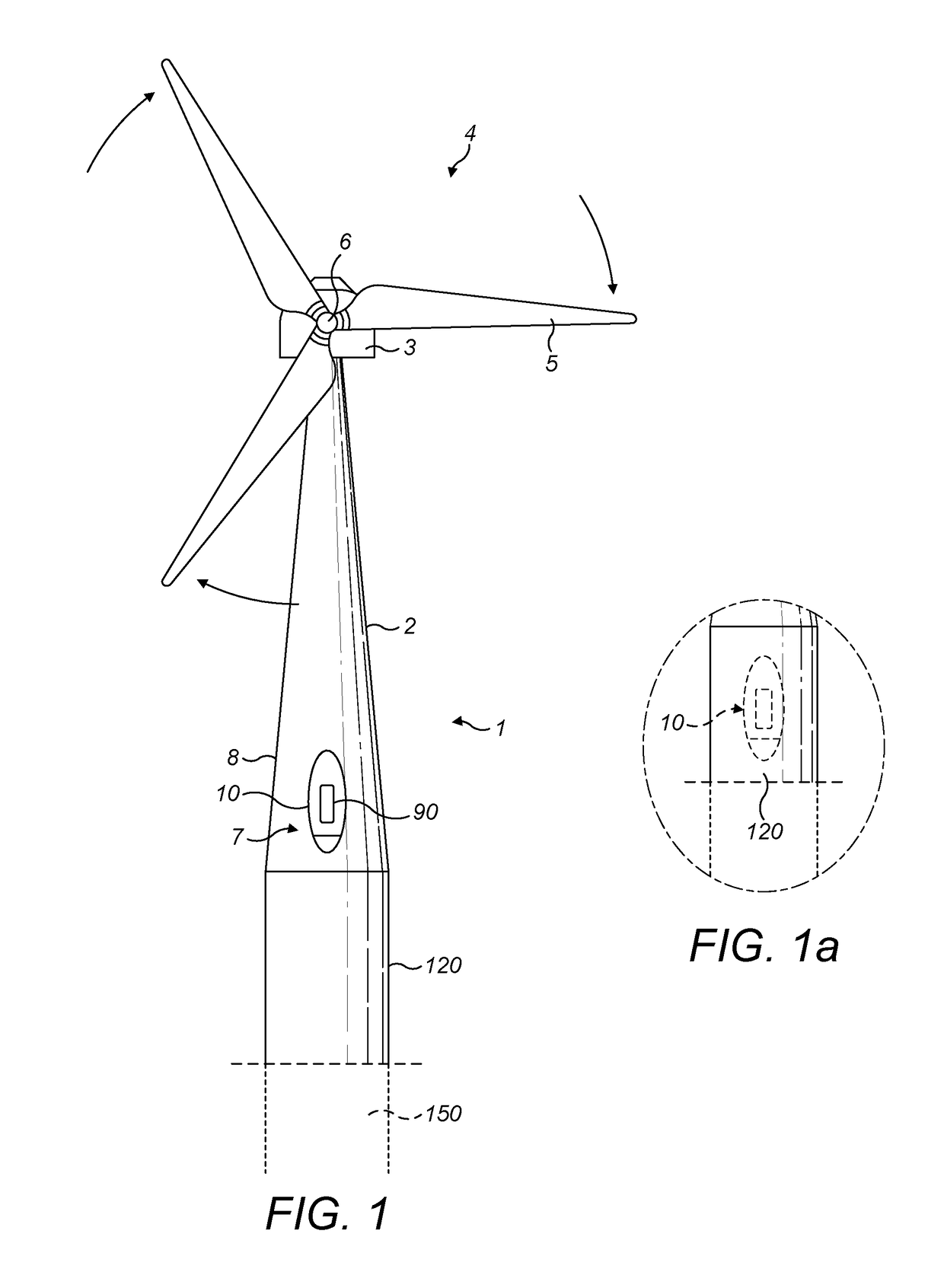
[0049]The tower 2 illustrated in FIG. 1 is shown with a schematically indicated access panel 10 according to aspects of the invention and fitted over a service aperture 7 in the tower wall 8. In FIG. 1, the service aperture is provided in a base region of the tower 2. In FIG. 1a, the service aperture 10 is shown in a transition piece 120, also known as an intermediate segment, which may connect the tower to a jacket or to a monopile type foundation 150 suggested in the illustration in dotted lines. For the purposes of this disclosure, a base region of a tower may be deemed to include a transition piece or intermediate segment 150. In some aspects, an external platform may be provided in a base region of a tower 2, as suggested in FIG. 1. Alternatively, the service aperture 7 may be provided in a base region of a tower 2 close to a foundation near ground level. Also visible in the access panel 10 is an optional auxiliary door 90 which allows access for service personnel without requi...


PUM


Abstract

The invention relates to a wind turbine tower access panel, which panel is removably fixable at a service aperture in a tower wall to thereby close said aperture; said access panel being generally planar and extending radially about an axis normal thereto, said access panel comprising a set of two or more fixing elements configured to securely fix said access panel in place at a said aperture; wherein each said fixing element comprises an axial clamp, said clamp comprising an anchor fixed to said access panel, a clamping force adjuster and a clamp head having a clamping surface; said clamp head comprising a relatively deformable resilient material which deforms under an applied clamping load of said clamp thereby applying a clamping force to said tower wall.

Description

[0001]This invention relates to an access panel and to a method for securing an access panel at an aperture in a wind turbine tower wall. In particular, the invention relates to a removably fixable access panel at a wind turbine tower wall and to a method for securing same.[0002]A horizontal axis wind turbine is illustrated in FIG. 1 to which reference should now be made. Schematic FIG. 1 illustrates a wind turbine 1, comprising a wind turbine tower 2 on which a wind turbine nacelle 3 is mounted. A wind turbine rotor 4 comprising at least one wind turbine blade 5 is mounted on a rotor hub 6.[0003]The hub 6 is connected to the nacelle 3 through a shaft (not shown) extending from the nacelle front. The nacelle 3 can be turned, using a yaw drive positioned at the top of the tower 1, to change the direction in which the rotor blade hub 6 and the blades 5 are facing. The blades are aerodynamically profiled so that they experience a ‘lift’ or pressure from the wind as the wind flows past ...

Claims


Application Information

Patent Timeline
IPC IPC(8): E04H12/00F03D13/20E06B1/60
CPCE04H12/003E06B1/6046F03D13/20F05B2240/913F03D1/00F05B2230/60F05B2240/912F05B2280/5011F05B2280/5001Y02E10/728F03D80/50Y02E10/72Y02P70/50
Inventor OLLGAARD, BORGE
Owner VESTAS WIND SYST AS
Why Eureka
Try Eureka