Hot Beverage Container

a beverage container and hot beverage technology, applied in drinking vessels, domestic cooling devices, lighting and heating devices, etc., can solve the problems of long waiting time, significantly more complex and expensive use or manufacture, and inability to meet the needs of consumers, etc., to achieve convenient cleaning, expand the window of optimal temperature for consumption, and save production costs.

Inactive Publication Date: 2007-08-16
HANSEN DAVID SCOTT
View PDF33 Cites 15 Cited by
  • Summary
  • Abstract
  • Description
  • Claims
  • Application Information

AI Technical Summary

Benefits of technology

[0010]Through this design, one can have an inexpensive, reusable, and easily cleaned mug that allows immediate and continuous consumption of hot beverages. Furthermore, by allowing immediate consumption without cooling the entire beverage at once, the window of optimal temperature for consumption is expanded. Once the beverage cools to the point that the tube cooling system is unnecessary, the cup can be sipped from in a normal fashion.

Problems solved by technology

When I have made hot coffee, hot chocolate, or hot tea in the past I have always been annoyed that I had to wait several minutes until my beverage cools down.
What should be a pleasant experience is marred by the need to take scalding test sips, or alternatively risk waiting too long and resulting in cold coffee.
These methods do not allow for immediate and continuous consumption allowed by my invention.
Furthermore, they are significantly more complex and expensive to use or manufacture, two of them even incorporating valve systems.
However, these designs suffer from one or more of the following deficiencies: lack sufficient straw length to cool a liquid, the tubes are not designed to maximize cooling, the tubes are permanently enclosed making cleaning impractical, require disassembly to clean, the tubes are arranged in vertical loops requiring additional sucking before beverage is consumed, and are not designed to hold hot beverages.
U.S. Pat. No. 4,442,948 is similar to an embodiment of my invention, but does not allow cleaning without disassembly.
The articles described in U.S. Pat. No. 4,442,948 require removal of the inner cup to expose the tubing for cleaning, which in addition to being an extra step, adds risk of losing a piece and rendering the whole mug useless.

Method used


Image

  • Hot Beverage Container
  • Hot Beverage Container
  • Hot Beverage Container

Examples


Embodiment Construction

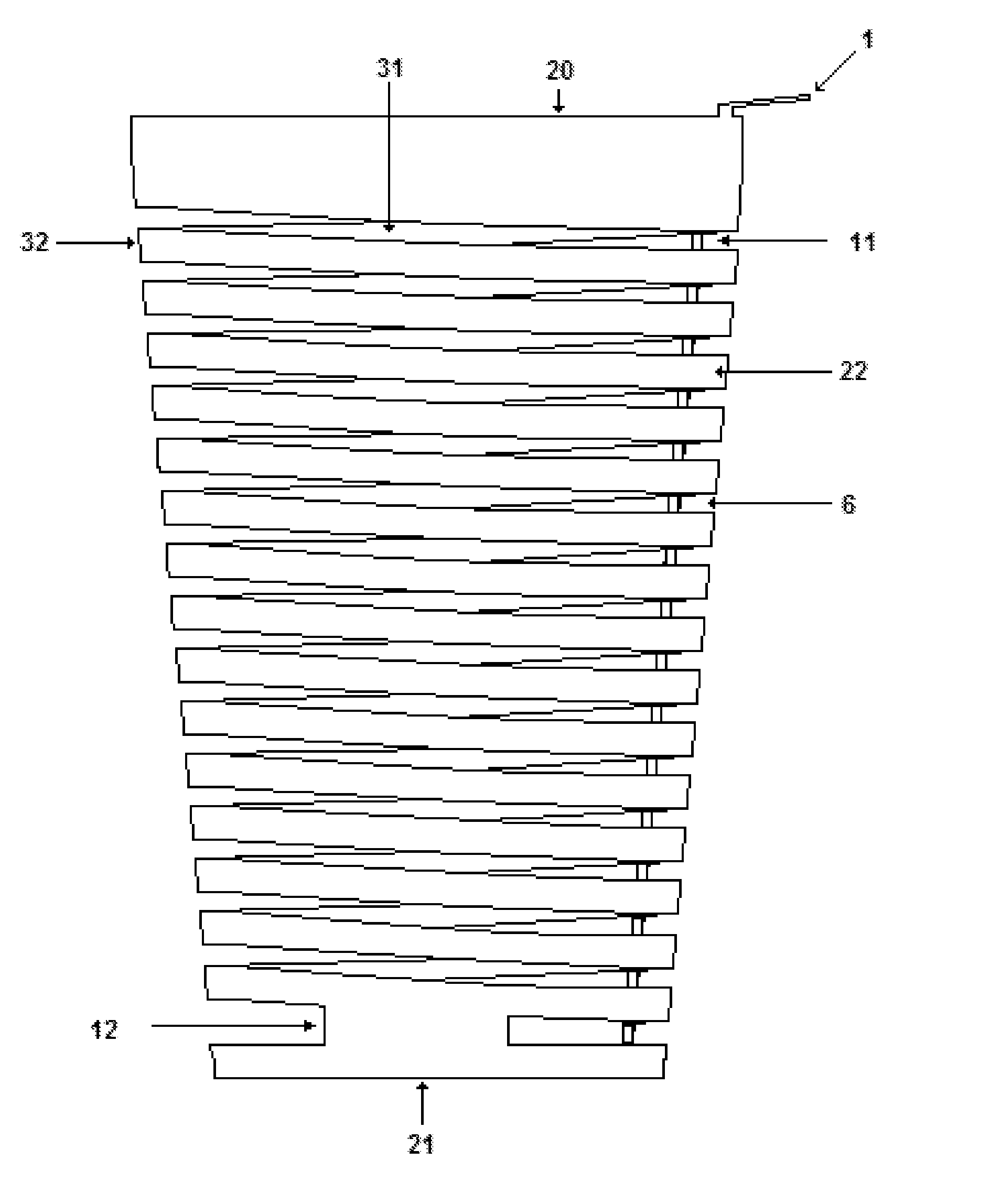
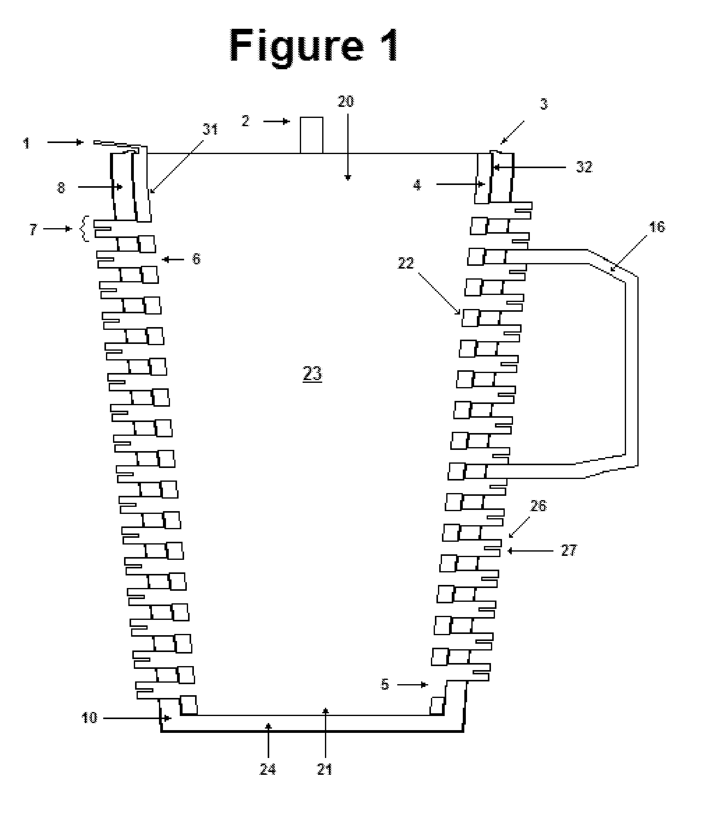
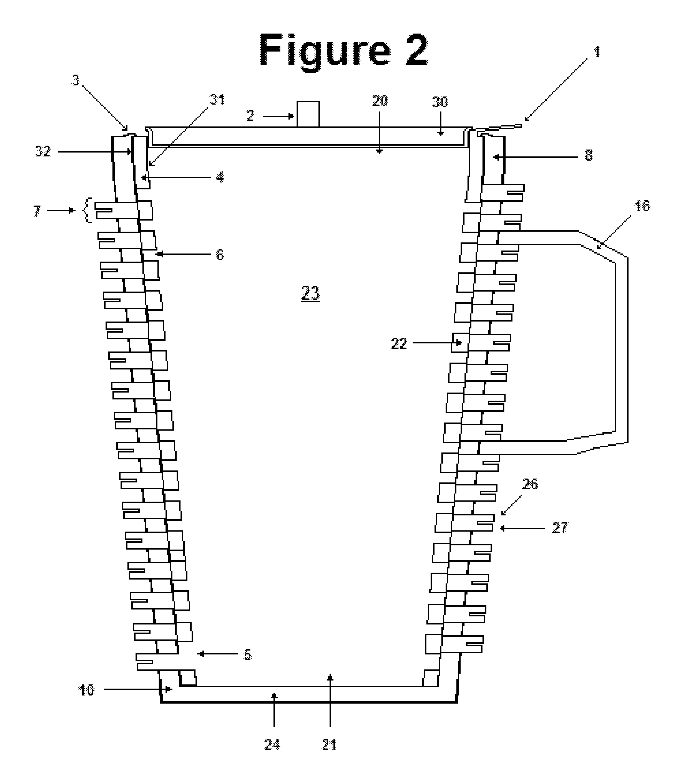
[0018]The beverage container of the invention is designed to overcome the shortcomings described in the prior art. It is a drinking container formed from two main parts—an inner core (4), shown separately in FIG. 3, and an outer shell (10), shown separately in FIG. 4. The other figures show the assembled cup, made up of the inner core (4) inside the outer shell (10).

[0019]Referring to the figures, the first par of the container is an inner core (4) with an open top (20), an open (as drawn) or closed bottom (21), and side walls (22) enclosing a central chamber (23). The inner core (4) is roughly cylindrical with a long gap (6) spiraling down from the inner surface (31) of the side walls (22) through to the outer surface (32) of the side walls (22), from the top (20) to the bottom (21). At the bottom (21) is a large gap (5) on both sides of the core (4) connected on the sides (12) such that the bottom tubing is exposed regardless of whether it is in consumption or cleaning orientation...


PUM


Abstract

A beverage container having an inner core and an outer shell, relatively rotatable such that a spiral groove in the inner core can be rotationally aligned with cooling flanges on the outside of the outer shell for cleaning, or rotated to close the cooling flanges, forming a cooling tube from the inside of the inner core to a drinking tube at the top of the container, thereby cooling a beverage that is drawn through the cooling flanges by radiating heat into the ambient environment.

Description

REFERENCE TO RELATED APPLICATIONS[0001]This application claims an invention which was disclosed in Provisional Application No. 60 / 766,787, filed Feb. 11, 2006, entitled “Never Too Hot Mug”. The benefit under 35 USC §119(e) of the United States provisional application is hereby claimed, and the aforementioned application is hereby incorporated herein by reference.BACKGROUND OF THE INVENTION[0002]1. Field of the Invention[0003]The invention pertains to the field of hot beverage containers. More particularly, the invention pertains to hot beverage containers that cool the liquid prior to consumption.[0004]2. Description of Related Art[0005]When I have made hot coffee, hot chocolate, or hot tea in the past I have always been annoyed that I had to wait several minutes until my beverage cools down. What should be a pleasant experience is marred by the need to take scalding test sips, or alternatively risk waiting too long and resulting in cold coffee. Having found no reusable mugs with su...

Claims


Application Information

Patent Timeline
Patent Type & Authority Applications(United States)
IPC IPC(8): A47G19/22
CPCA47G19/2288
Inventor HANSEN, DAVID SCOTT
Owner HANSEN DAVID SCOTT
Why Eureka
Try Eureka