Metering and dispensing closure

a technology of metering and dispensing, which is applied in the direction of liquid transfer devices, movable measuring chambers, instruments, etc., can solve the problems of not providing the prior art does not provide a metering and dispensing closure, and the inability to effect the desired internal stirring action of the container contents, etc., to achieve accurate measurement of powder or granular materials

Active Publication Date: 2007-08-16
JOHNSONDIVERSEY INC
View PDF43 Cites 40 Cited by
  • Summary
  • Abstract
  • Description
  • Claims
  • Application Information

AI Technical Summary

Benefits of technology

[0023] In some embodiments, the cap and first moveable member have a substantially concave shape. This shape can help to substantially fully deplete dispensable materials from a container. In some embodiments, the second movable member also has a substantially concave shape.
[0031] Another object is a powder dispensing device which can provide a seal for the powder being dispensed.
[0034] Still yet another object is a dispensing device of the foregoing type which can accurately measure a powder or granular material being dispensed.

Problems solved by technology

There are problems with a rotatable measuring piece and stationary feed pieces.
These cannot effect a desired internal stirring action of the container contents.
The prior art does not provide a metering and dispensing closure which is connectable to a container and affords suitable sealing for powder materials which are hygroscopic.
There are two important limitations with these systems; the feed-rate is very inconsistent, and the powder formulations are limited.
Stated another way, because of the feed-rate variation, “spray / screen” powder dispensing systems normally can not be used in applications where a repeatable dose is required.
The “spray / screen” dispensers work only with a limited range of powders and formulations.
Detergents, the most commonly fed powders, are limited to formulations that will not create excess exothermic heat if the spray should penetrate into the powder.
This has typically meant that the caustic (typically NAOH or KOH) level needs to be kept below about 40% to prevent the possibility of steam generation within the container which can be a safety issue.
Many powders simply cannot be fed at all using the “spray / screen” method.

Method used


Image

  • Metering and dispensing closure
  • Metering and dispensing closure
  • Metering and dispensing closure

Examples


Embodiment Construction

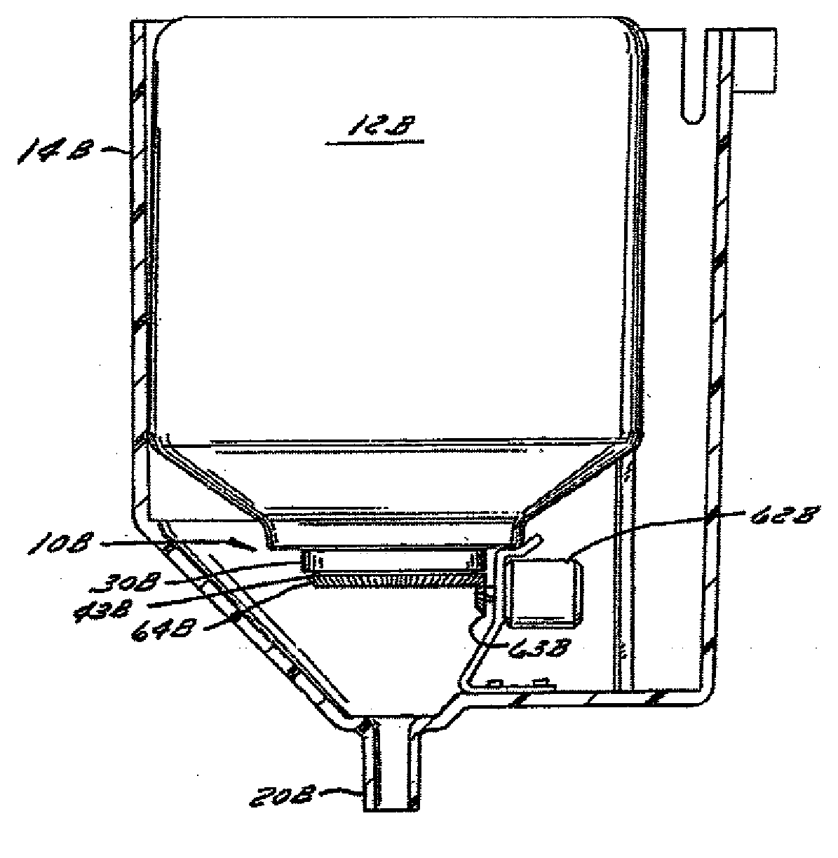
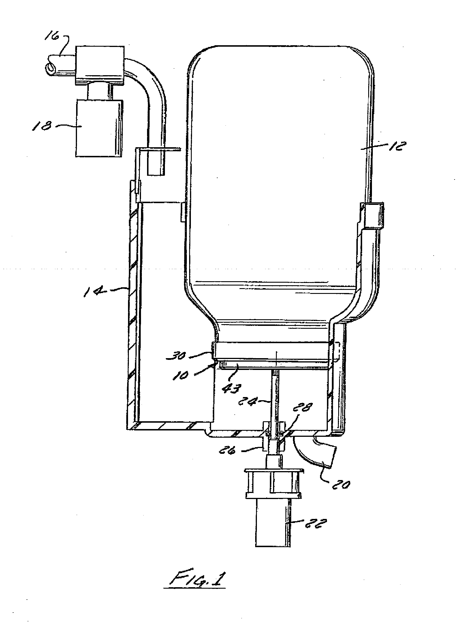
[0092] Referring to FIGS. 1-5, the metering and dispensing closure generally 10 is shown in conjunction with a container 12 supported in a dispenser assembly or receptacle 14 for housing the closure 10. A water intake conduit 16 controlled by solenoid valve 18 is utilized to introduce water into the dispenser assembly or receptacle 14. A water solution outlet conduit 20 is also in communication with the dispenser assembly or receptacle 14. A drive member 22 drives a drive shaft 24, the drive shaft being journalled in the collar 26 with a seal 28.

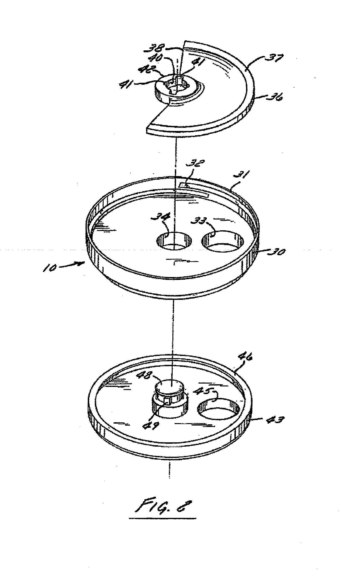
[0093] Referring to FIG. 2, it is seen that the metering and dispensing closure generally 10 is composed of three basic components. There is a cap member 30 with an upstanding wall 31 and internal threads 32 for engaging complementary threads on the container 12. There is also a rotatable disk 36 with a raised peripheral wall 37 as well as a cutaway portion 38. Rotatable disk 36 is seated inside the cap member 30. The third component is a r...


PUM


Abstract

A metering and dispensing closure for a container wherein two rotatable disks rotate in conjunction with a stationary cap member to afford accurate measuring of a powder material and dispensing of it. The disks and the container cap afford a consistent measuring of the powder material, as well as provide a variety of drive members which can be utilized with the dispensing closure.

Description

CROSS-REFERENCES TO RELATED APPLICATIONS [0001] This is a continuation-in-part of U.S. patent application Ser. No. 11 / 404,518, filed Apr. 14, 2006, which is a continuation-in-part of U.S. patent application Ser. No. 10 / 709,449, filed May 6, 2004, now U.S. Pat. No. 7,090,098.BACKGROUND [0002] The field of the invention is metering and dispensing devices for a powder or granular material. More particularly, it relates to a powder dispensing closure which is connected to a container and can dispense accurate amounts of the powder into a liquid or container. [0003] Dispensers of the type concerned with in this invention are disclosed in U.S. Pat. No. 4,032,050 and No. 5,469,992. Both of these dispensers disclose a rotatable metering disk (80 and 20, respectively) for materials to be dispensed. There are problems with a rotatable measuring piece and stationary feed pieces. These cannot effect a desired internal stirring action of the container contents. Without this action, a significant...

Claims


Application Information

Patent Timeline
Patent Type & Authority Applications(United States)
IPC IPC(8): G01F11/10G01F11/46
CPCB65D83/06B65D47/04G01F11/46
Inventor WEBSTER, TYSON L.DEEDS, M. RINLEYLIVINGSTON, JAMES W.SWAIN, ANDYHOLDEN, DAVIDBIRD, KENNETH J.
Owner JOHNSONDIVERSEY INC
Why Eureka
Try Eureka