MEMS switch with bistable element having straight beam components

a technology of bistable elements and switches, applied in thermal micromechanical switches, contacts, instruments, etc., can solve the problems of falling dramatically short of the rf power level, inherently unstable movement between, and potentially low cost of the devi

Inactive Publication Date: 2007-08-16
SLICKER JAMES MELVIN +2
View PDF10 Cites 28 Cited by
  • Summary
  • Abstract
  • Description
  • Claims
  • Application Information

AI Technical Summary

Benefits of technology

[0019] In a variation of the invention, the first set of electrical signal contacts is mounted on resilient supports which are actuated by the auxiliary MEMS actuator, without the need for the latch. Even in this variation of the inven...

Problems solved by technology

MEMS devices are potentially low cost devices, due to the use of microelectronic fabrication techniques.
In addition, the structure in this US patent has an inherently unstable movement between the two stable states, requiring a double support structure to remedy the problem.
Commercially available MEMS switches are electrostatically actuated...

Method used


Image

  • MEMS switch with bistable element having straight beam components
  • MEMS switch with bistable element having straight beam components
  • MEMS switch with bistable element having straight beam components

Examples


first embodiment

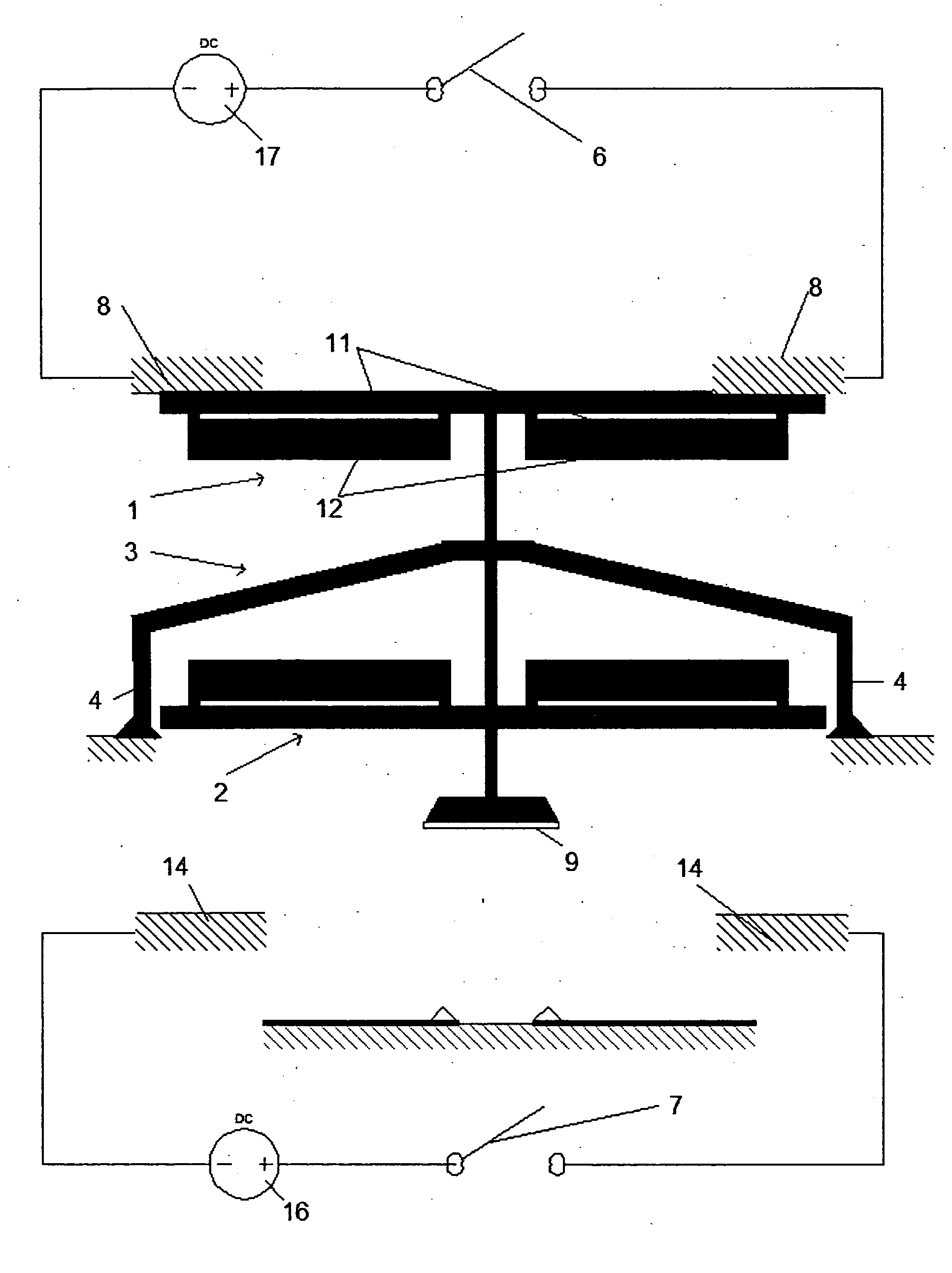
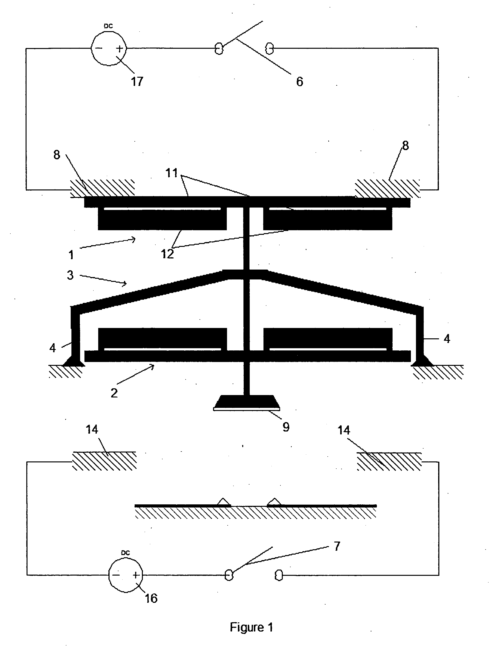
[0041] FIGS. the 1-4 show the switch at four stages of switching from one stable state to the alternate stable state. Referring to FIG. 1, the switch starts out in stable state 1. The switch contact means 9 cooperating with the bistable element 3 closes signal contacts 10 in the UP position. The MEMS switch structure as shown consists of ETC actuators 1 and 2 and bistable element 3 which is attached to the substrate through compliant supports 4. Compliant supports 4 also keep the bistable element 3 in the “up” position when electrical switches 6 and 7 are open. The bistable element remains in the up position when no force is applied to it because the element is unstressed along its length, and movement downward requires the bistable element 3 to be urged to move to an increased energy level. ETC actuator 1 rests against fixed supports 8. Fixed supports 8 also-are connected to voltage source 17 via switch 6.

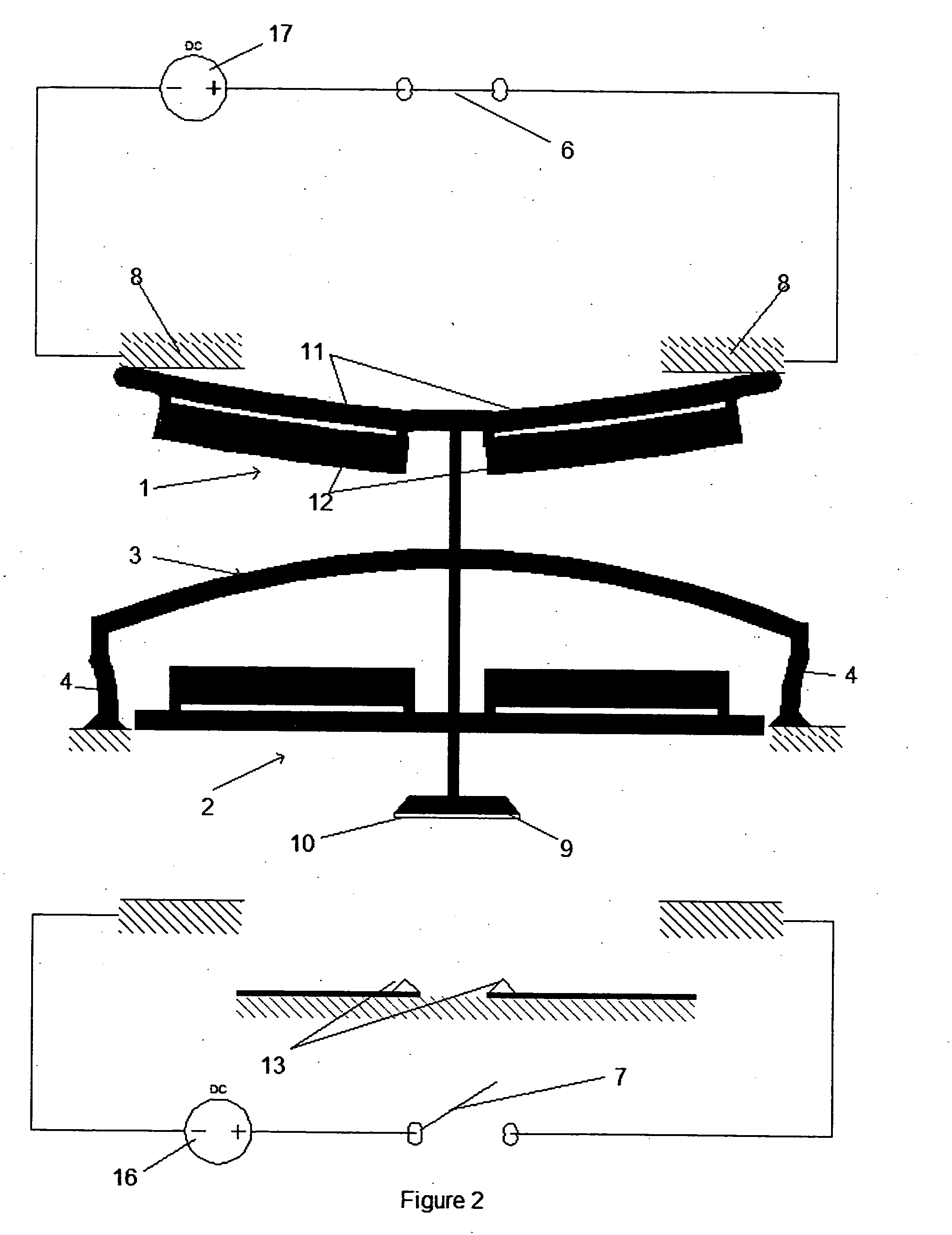
[0042] Referring to FIG. 2, the start of actuation occurs with the closure of...

second embodiment

[0045] FIGS. the 5-7 show the switch at three stages of switching from one stable state to the second stable state. Referring to FIG. 5, the switch starts out in stable state 1. The switch consists of ETC actuators 1 and 2 and bistable element 3. The bistable element 3 is attached to the substrate through compliant supports 4. Compliant supports 4 also keep the bistable structure 3 in the “up” position when electrical switches 6 and 7 are open. ETC actuator 1 is attached to the substrate by fixed supports 8. ETC actuator 1 also is connected to voltage source 17 via switch 6. ETC actuator 2 is attached to the substrate by fixed supports 14. ETC actuator 2 also is connected to voltage source 16 via switch 7. When the switch structure is in the first stable state, switch contact means 9 shorts signal contacts 10. When the switch structure is in the second stable state, switch contact means 9 shorts signal contacts 13.

[0046] Referring to FIG. 6, the start of actuation occurs with the cl...


PUM


Abstract

A MEMS switch of the type having a substrate and a bistable element, uses a structure for the bistable element having first and second substantially straight beam members that are bridged by an optional switch contact member. The switch contact member may be actuated to close a pair of fixed electrical contacts by an actuator means. The actuator means as described comprises electro-thermally compliant actuators. However, other types of actuators including thermo-pneumatic, thermal bimorphic, piezoelectric, electrostatic, fluidic, electromagnetic and phase change actuators may be used. The bistable element is structured to be moved between a first stable state and a second stable state by the selective urging action of two opposing actuators. The actuators, if the electo-thermal compliant type, may comprise first and second bound and spaced electrically conductive beams connected in parallel and supplied with an electrical current. The electrical current is shared by the two conductive beams unequally, causing a differential linear expansion in the two beams and consequential buckling. The buckling action of the bound and spaced beams is used to cause buckling movement of the bistable element from one stable state to the other. In a preferred embodiment, first and second support members, at least one of which is compliant, are interposed between the ends of the bistable element and the substrate. In an embodiment, an optional latch mechanism is used to initially make the bistable element go into one stable state. The latch mechanism may be operated by an auxiliary actuator.

Description

RELATED APPLICATIONS [0001] This application is related to and claims priority from U.S. Provisional Application 60 / 499,755, filed on Sep. 4, 2003, and U.S. Provisional Application 60 / 499,895, filed on Sep. 4, 2003, both of which are incorporated herein by reference.FIELD OF THE INVENTION [0002] This invention generally relates to Microelectro-mechanical System (MEMS) devices, and more particularly to MEMS devices with a bistable element having at least one straight beam component. BACKGROUND OF THE INVENTION [0003] Microelectro-mechanical systems (MEMS) have recently been developed as alternatives for conventional electromechanical devices such as switches, actuators, valves and sensors. MEMS devices are potentially low cost devices, due to the use of microelectronic fabrication techniques. New functionality may also be provided because MEMS devices can be much smaller than conventional electromechanical devices. [0004] U.S. Pat. No. 5,955,817 to Vijayakumar, et al. entitled “Therm...

Claims


Application Information

Patent Timeline
IPC IPC(8): G02B26/00H01H
CPCH01H1/0036H01H2037/008H01H2001/0042H01H1/20
Inventor SLICKER, JAMES MELVINSURIANARAYANAN, ANANTHAKRISHNANANANTHASURESH, G K
Owner SLICKER JAMES MELVIN
Why Eureka
Try Eureka