

Subminiature optical system
a sub-miniature and optical system technology, applied in the field of imaging optical systems, can solve the problems of limited design flexibility and unsatisfactory optical capability, and achieve the effects of less manufacturing cost, easy manufacturability, and light weigh
- Summary
- Abstract
- Description
- Claims
- Application Information
AI Technical Summary
Benefits of technology
Problems solved by technology
Method used
Image

Examples
example 1
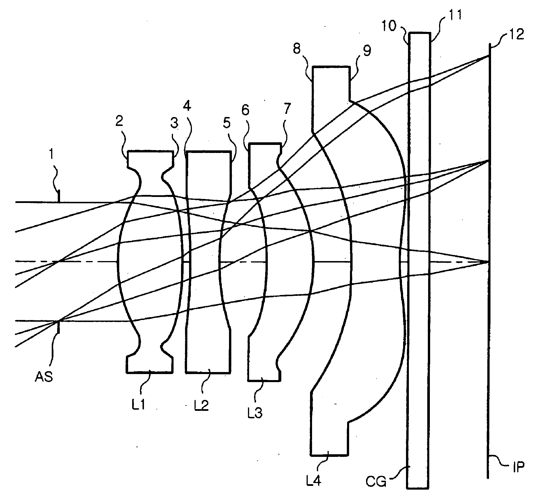
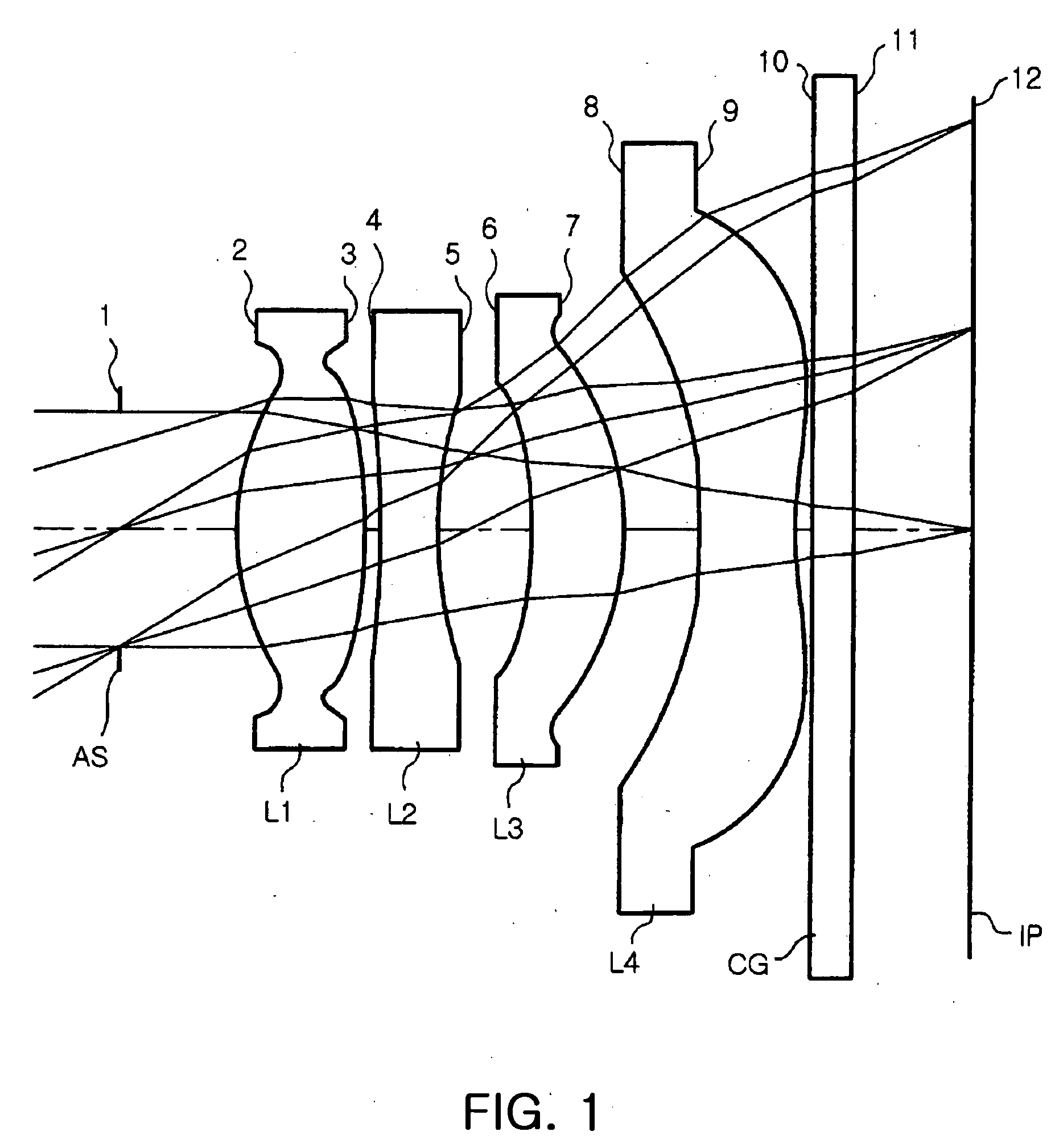
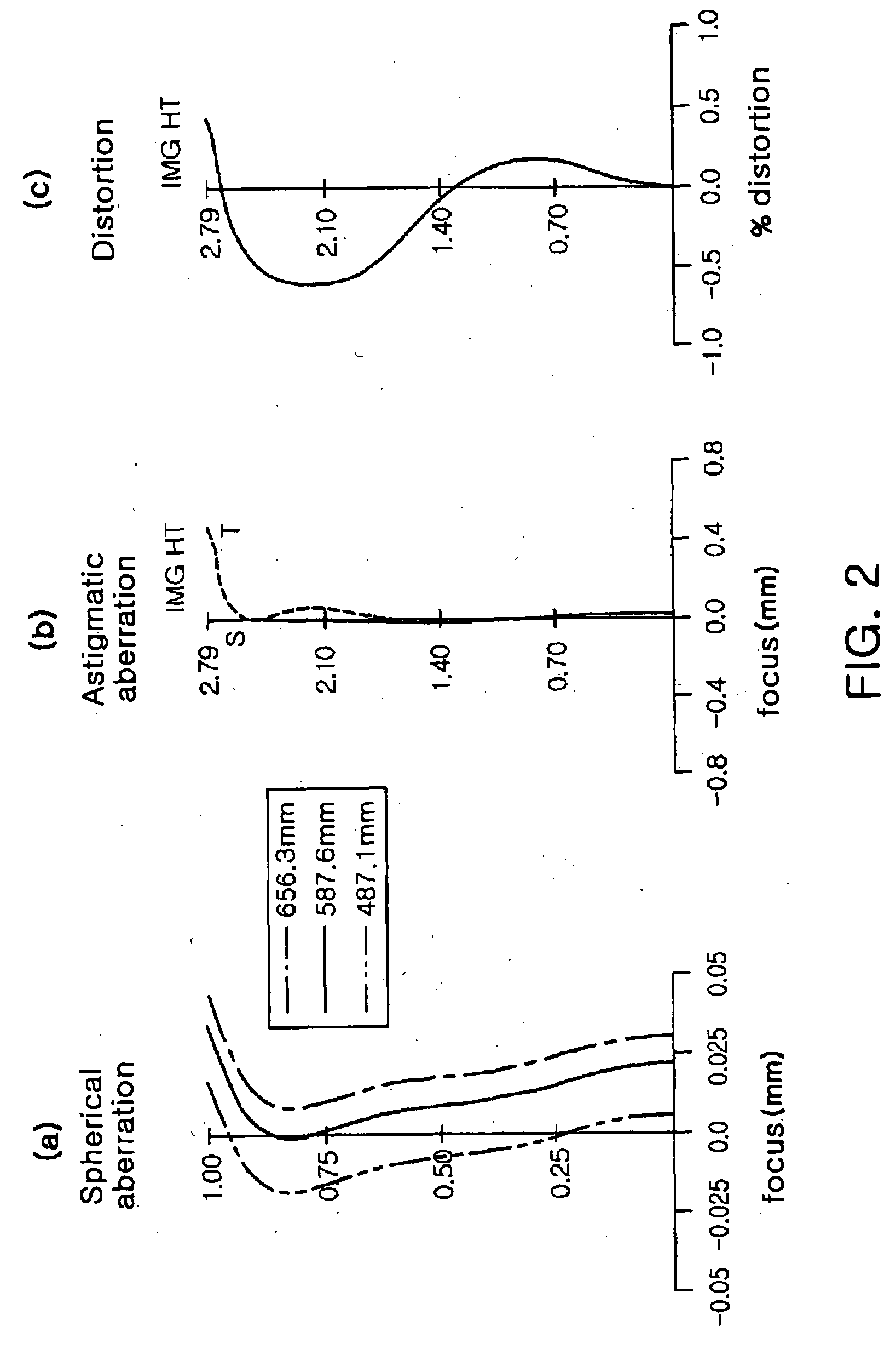
[0067]Table 1 below shows exemplary aberrations of a subminiature optical system according to Example 1 of the invention. FIG. 1 is a diagram illustrating lens arrangement of the subminiature optical system according to Example 1 of the invention. FIGS. 2a to 2c are aberrational diagrams illustrating the optical system shown in Table 1 and FIG. 1. Meanwhile, in the following astigmatic aberration diagram, “S” denotes sagittal and “T” denotes tangential.
[0068]In Example 1, an F number FNo is 2.8, an angle of view is 60 degree, a distance TL between the aperture stop and the image plane is 6.07 mm, and an effective focal distance f of the optical system is 4.6 mm. Also, in Example 1, the first lens L1, the third lens L3, and the fourth lens L4 are made of plastics.
TABLE 1Radius ofPlaneAbbePlaneCurvatureInterval tRefractiveNumberNo.R(mm)(mm)Index ndvdRemarks1∞0.800000Aperture stop*21.709080.8800001.51764.2First lens*3−3.756900.1000004−10.000000.4000001.71729.5Second lens53.000000.65000...
example 2
[0070]Table 3 below demonstrates aberrations of a subminiature optical system according to Example 2 of the invention. FIG. 3 is a diagram illustrating lens arrangement of the subminiature optical system according to Example 2 of the invention. FIGS. 4a to 4c are aberrational diagrams illustrating the optical system shown in Table 3 and FIG. 3.
[0071]In Example 2, an F number FNo is 2.8, an angle of view is 60 degree, a distance TL between the aperture stop and an image plane is 5.96 mm, an effective focal distance f of the optical system is 4.85 mm. Also, in Example 2, the first, third and fourth lenses L1, L3 and L4 are made of plastics.
TABLE 3Radius ofPlaneAbbePlaneCurvatureIntervalRefractiveNumberNo.R(mm)t(mm)Index ndvdRemarks1∞0.050000Aperture stop*21.774850.8000001.52955.8First lens*3−8.374630.1300004−20.984580.4000001.71729.5Second lens53.061860.850000*6−2.412890.9071171.52955.8Third lens*7−1.211720.120000*85.106470.7000001.52955.8Fourth lens*91.614730.43186110∞0.3000001.51764...
example 3
[0073]Table 5 below indicates aberrations of a subminiature optical system according to Example 3 of the invention. FIG. 5 is a diagram illustrating lens arrangement of the subminiature optical system according to Example 3 of the invention. FIGS. 6a to 6c are aberrational diagrams illustrating the optical system shown in Table 5 and FIG. 5.
[0074]In Example 3, an F number FNo is 2.8, an angle of view is 60 degree, a distance TL between the aperture stop and an image plane is 7.22 mm, and an effective focal distance f of the optical system is 6 mm. Also, in Example 3, the first, third and fourth lenses L1, L3 and L4 are made of plastics.
TABLE 5Radius ofPlanePlaneCurvature RInterval tRefractiveAbbeNo.(mm)(mm)Index ndnumberRemarks1∞0.058564Aperturestop*22.078840.9370211.52955.8First lens*3−9.809000.1522664−24.578730.4685101.75527.5Second lens53.586280.995584*6−2.826161.0624851.52955.8Third lens*7−1.419260.140553*85.981080.8198931.52955.8Fourth lens*91.891290.50582810∞0.3513831.51764.2C...
PUM
 Abstract
Description
Claims
Application Information