Pipe joint

a pipe joint and pipe technology, applied in the direction of rod connections, fastening means, manufacturing tools, etc., can solve the problems of spoiling the appearance and affecting the attractiveness of the pipes, and achieve the effect of maintaining the attractiveness of the coupled pipes, and strong resistance to pulling tension

Inactive Publication Date: 2007-08-16
YAZAKI IND CHEM CO LTD
View PDF0 Cites 4 Cited by
  • Summary
  • Abstract
  • Description
  • Claims
  • Application Information

AI Technical Summary

Benefits of technology

[0012] According to the pipe joint of the present invention as stated in claim 1, since the fixing means, such as bolts and nuts, are arranged at the central region of the pipe, the use of bolts and nuts of large diameters is made possible and, while the elastic members increase in diameter through clamping of the bolts and nuts to be pressed against the whole inner periphery of the pipe, the bent back claws of the fixing device bite into the inner periphery of the insertion parts of the joint body, which makes it possible to realize a strong resistance against pulling tension without increasing the contact length of the joint with the pipes, and to maintain the attractiveness of the coupled pipes without leaving through holes in the pipes and the joint, or any clearance in the joint.
[0013] According to the pipe joint of the present invention as stated in claim 2, one end of the insertion parts is pressed against the inner periphery of the pipe through a wedge action due to the displacement of the push pin caused by the turn of the elliptic pin, which makes it possible to realize a strong resistance against pulling tension without increasing the contact length of the joint with the pipes, and to maintain the attractiveness of the coupled pipes while leaving but one through hole in the pipe.
[0014] According to the pipe joint of the invention stated in claim 3, in a way similar to that of the invention stated in claim 2, one end of the insertion parts is pressed against the inner periphery of the pipe through a wedge action due to displacement of the push pin caused by the turn of the elliptic pin, which makes it possible to realize a strong resistance against pulling tension without increasing the contact length of the joint with the pipes, and to maintain the attractiveness of the coupled pipes while leaving but one through hole in the pipe.
[0015] According to the pipe joint of the invention stated in claim 4, one end of each of the insertion parts is pressed against the inner periphery of the pipe through a wedge action due to displacement of the plurality of the push pins caused by the screwing-in of the push screw, which makes it possible to realize a strong resistance against pulling tension, without increasing the contact length of the joint with the pipes, and to maintain the attractiveness of the coupled pipes since coupling of a plurality of pipes can be effected by screwing a single push screw while leaving but one through hole in the pipe joint body. PREFERRED EMBODIMENTS OF THE INVENTION
[0016] The joint bodies of the pipe joints according to the present invention as stated in claims 1 through 4 can be used in various configurations, such as a straight line type, an L-shape type, a T-shape type or a cross type, to connect 2 to 5 pipes together without restricting the angle between adjacent pipes to a right angle. The joint bodies of the pipe joints according to the present invention as stated in claims 1 through 4 are made of synthetic resin reinforced with glass fiber or of a metal material such as aluminum.
[0017] A material such as urethane rubber is used as the elastic member in the fixing device of the pipe joint according to the present invention as stated in claim 1. The stopper piece of the fixing device is made of a metal of relatively high hardness. For mounting the fixing device in the pipe, the fixing device is inserted to a position from the end of the pipe approximately corresponding to the length of the insertion part of the joint body with the stopper piece directed toward the end, and an appropriate tool for turning screws or nuts is used.

Problems solved by technology

In any of the above-mentioned prior art pipe joints, however, the pressing force of the arm lever and the sub-lever or the first and the second connection bushes against the inner surfaces of the pipes is effected by a repulsive force exerted on the arm lever and the sub-lever through screws or on the first and the second connection bushes through bolts and nuts, and, since the structure does not permit the use of screws or bolts of large size, the contact length between the arm lever and the sub-lever, or between the first and the second connection bushes must be increased to accommodate more screws or bolts and nuts to obtain sufficient resistance to pulling tension.
Furthermore, in the former type of pipe joints, two or more of the through holes for a wrench remain on the surface of the pipes, spoiling the appearance.
On the other hand, in the latter type of pipe joints, the clearance observed between the first and the second connection bushes exposed from the pipes is also detrimental to the attractiveness of the pipes.

Method used


Image

  • Pipe joint
  • Pipe joint
  • Pipe joint

Examples


embodiment 1

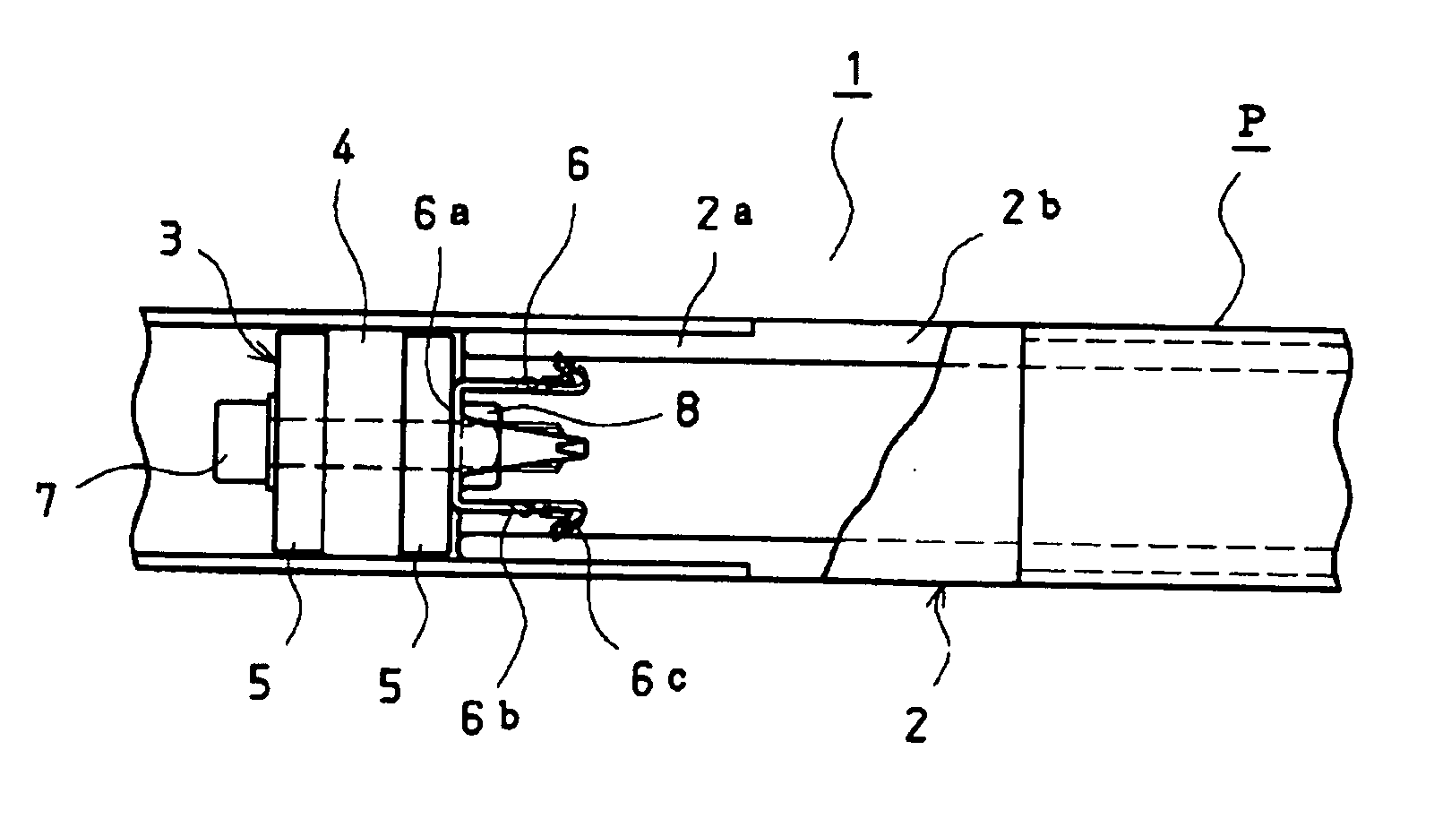
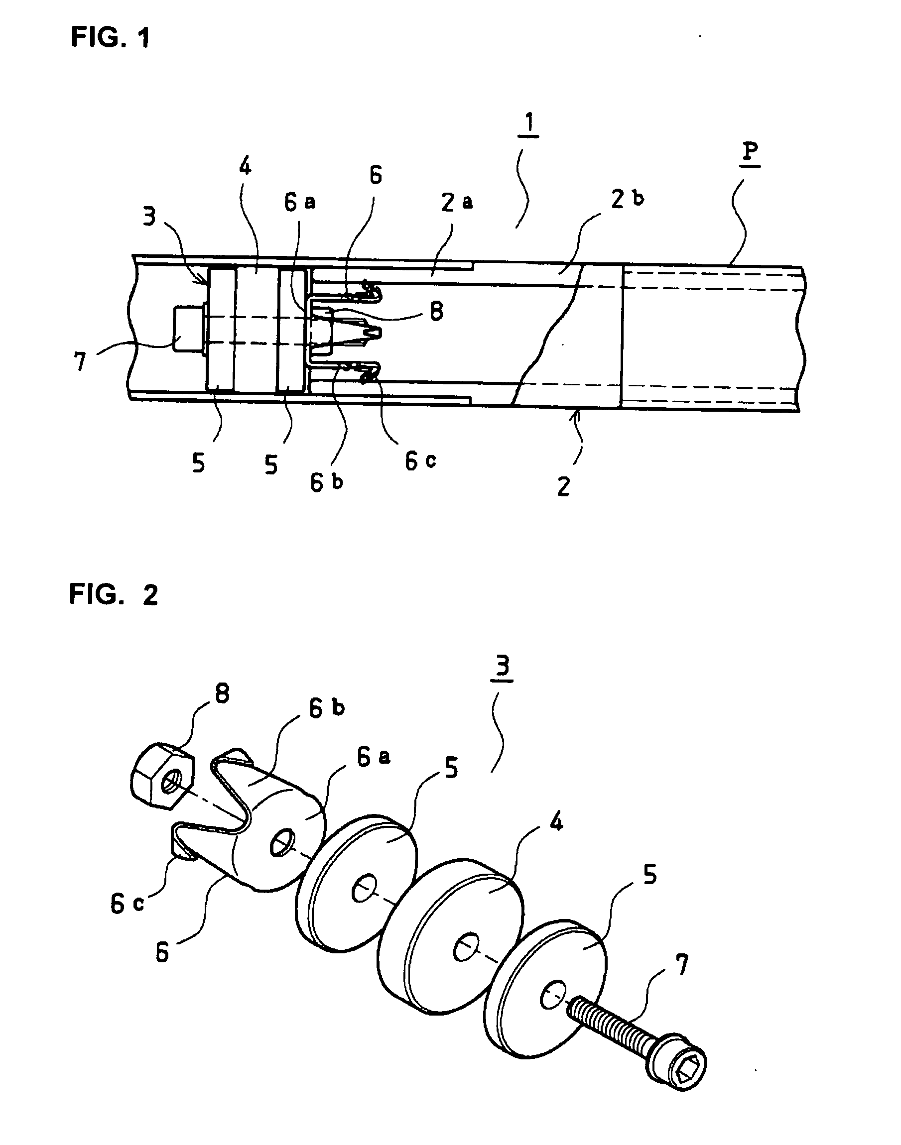
[0021]FIG. 1 is a side elevational view with a broken part of the structure of the pipe connection effected with the pipe joint according to the present invention as stated in claim 1.

[0022] The pipe joint 1 of the present invention as stated in claim 1 comprises a joint body 2 consisting of two insertion parts 2a connected in a straight line through a connection part 2b, which consists of a single cylinder having the same outer diameter with the pipes P. The joint body 2 is made of a synthetic resin material reinforced with glass fiber or a metal material such as aluminum.

[0023] Numeral 3 designates a fixing device which, together with the joint body 2, constitutes the pipe joint of the present invention as stated in claim 1, and consists of an elastic member 4 of a circular disc made of a material like urethane rubber having an outer diameter nearly equal to the inner diameter of pipe P, clamp discs 5, which are provided on both sides of the elastic member 4 and have approximate...

embodiment 2

[0028]FIG. 6 is a side elevational view with a broken part showing the structure of the pipe connection effected with the pipe joint according to the present invention as stated in claim 2, FIG. 7 is a view seen in the direction of VII-VII arrows of FIG. 6 and FIG. 8 is a diagonal view of disassembled members of the structure of FIG. 6.

[0029] The pipe joint 14 of the present invention as stated in claim 2 comprises a joint body 18 consisting of insertion parts 18a which, having a cylindrical form to be fitted in the ends of the pipes P, are formed on the inner periphery of one end thereof with a taper 15 that decreases in diameter toward the other end, on the same end are formed with a number of axially extending slits 16, are further provided with a through pin hole 17 perpendicular to the axis thereof, and are connected together in a straight line at the other ends thereof through a connection part 18b consisting of a single cylinder having the same outer diameter as the pipe P. ...

embodiment 3

[0037]FIGS. 11, 12 and 13 are respectively a side elevational view with a broken part to show structure of the pipe connection effected with the pipe joint according to the present invention as stated in claim 3, a view seen in the direction of XII-XII arrows of FIG. 11 and a diagonal view of the disassembled members of the structure of FIG. 11.

[0038] The pipe joint 27 of the present invention as stated in claim 3 comprises a joint body 29 consisting of insertion parts 29a, which, having a cylindrical form to be fitted in the ends of the pipes P, are formed on one end thereof with a number of axially extending slits 28, and which are connected together in a straight line at the other ends thereof through a connection part 29b consisting of a single cylinder having the same outer diameter as the pipe P. This joint body 29 is made of a synthetic resin material reinforced with glass fiber or a metal material such as aluminum.

[0039] In the insertion part 29a of the joint body 29 is fi...


PUM


Abstract

The present invention provides a pipe joint which gives a sufficient resistance against pulling tension without increasing contact length with pipes and which allows an attractive appearance for the coupled pipes. The present invention comprises a joint body consisting of a plurality of insertion parts connected together through a connection part consisting of a single cylinder or a plurality of cylinders having the same diameter as the pipes, and a fixing device which consists of an elastic member of a form of circular disc having a diameter approximately equal to the inner diameter of the pipes, clamp discs arranged on both sides of the elastic member, a stopper piece which, being arranged adjacent one of the clamp discs, has a plurality of legs extending axially from the periphery of a circular plate and is provided at the ends of the legs bent back claws which can bite in the inner periphery of the insertion parts, and a bolt and a nut which, lead through the central holes of the elastic member, the clamp discs and the stopper piece, fasten them tightly, the fixing device being fitted in the pipe with the stopper piece placed at a position from the end of the pipe corresponding to the length of the insertion part.

Description

FIELD OF THE INVENTION [0001] This invention relates to a pipe joint, and more particularly, to an inner-type pipe joint for detachably connecting cylindrical pipes. BACKGROUND OF THE INVENTION [0002] In the prior art, joint units as pipe joints of this type are well known that are comprised of a connecting piece having at least two mounting faces, an arm lever detachably screwed to the mounting faces, and a sub-lever attached to the arm lever along its axis in such a manner that the sub-lever is screwed to the arm lever so as to be movable radially with respect to it. [0003] Another type of pipe joints is known to include a pair of first and second connection bushes which are inserted in the ends of pipes to be coupled together, and a bolt and nuts which extend through the first connection bush at the center of the pair of bushes so as to force the second bush away from the first. [0004] In any of the above-mentioned prior art pipe joints, however, the pressing force of the arm lev...

Claims


Application Information

Patent Timeline
Patent Type & Authority Applications(United States)
IPC IPC(8): F16B7/04F16B7/02F16B7/18F16B7/20F16B7/22
CPCF16B7/025F16B7/0413Y10T403/7056F16B7/0466F16B7/22F16B7/046
Inventor MINOWA, ISAMU
Owner YAZAKI IND CHEM CO LTD
Why Eureka
Try Eureka