Wind turbine rotor blade

a technology of wind turbines and rotor blades, which is applied in the direction of rotary propellers, machines/engines, reaction engines, etc., can solve the problems of insufficient buckling strength of shells, low rigidity, and relatively light shells

Active Publication Date: 2007-08-16
GENERAL ELECTRIC CO
View PDF16 Cites 74 Cited by
  • Summary
  • Abstract
  • Description
  • Claims
  • Application Information

AI Technical Summary

Problems solved by technology

However, the shells are relatively light and have only low rigidity.
Therefore, the stiffness and rigidity as well as the buckling strength of the shells is not sufficient.

Method used


Image

  • Wind turbine rotor blade
  • Wind turbine rotor blade
  • Wind turbine rotor blade

Examples


Embodiment Construction

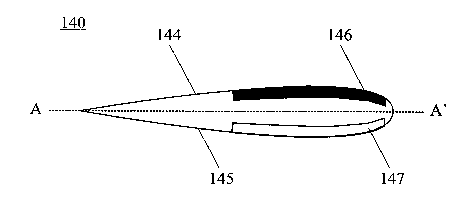
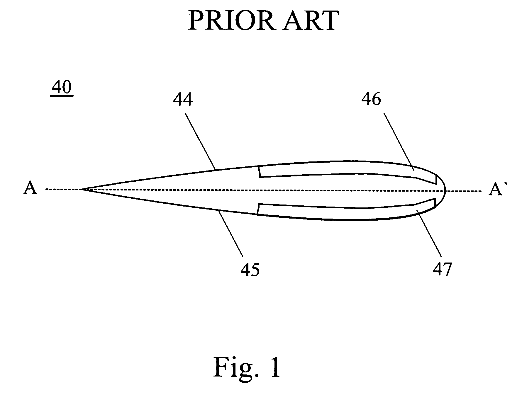
[0014] As indicated above, it is known for sparcaps to extend substantially over a longitudinal length of a rotor blade. A cross-sectional view of such a conventional rotor blade 40 is shown in FIG. 1. Therein, rotor blade 40 includes a pressure side shell 44 and a suction side shell 45 which are reinforced by pressure side and suction side sparcaps 46, 47, respectively. Pressure side sparcap 46 and suction side sparcap 647 are made of a glass fiber reinforced polymer. However, glass fiber reinforced polymer has low stiffness and high density so that the conventional sparcaps shown in FIG. 1 are heavy and do not add sufficient stiffness.

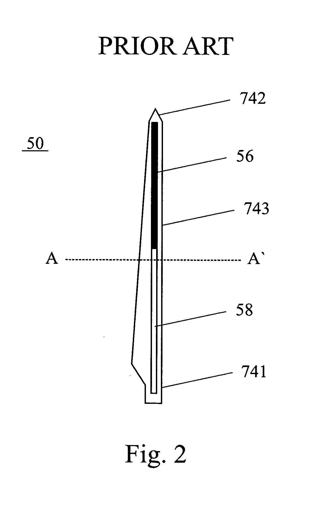
[0015] WO 03 / 093672 discloses a wind turbine rotor blade 50 as it is shown in FIG. 2. Therein, sparcaps 46 and 47 have a first section 56 purely made of carbon fiber reinforced polymer and a second section 58 purely made of glass fiber reinforced polymer. Carbon fiber reinforced section 56 is arranged at a tip end side of rotor blade 50 whereas glas...


PUM


Abstract

A wind turbine rotor blade includes a pressure side sparcap having a carbon fiber reinforced section extending substantially a full longitudinal length of the pressure side sparcap and a suction side sparcap having a glass fiber reinforced section extending substantially a full longitudinal length of the suction side sparcap.

Description

BACKGROUND OF THE INVENTION [0001] This invention relates generally to a wind turbine rotor blade, and more particularly, to a prefabricated sparcap of a wind turbine rotor blade. [0002] Wind turbine blades are typically made by means of two blade shell halves, of fiber reinforced polymer. When molded the two halves are glued together along the edges and via two bracings, which prior thereto have been glued to the inner face of one the blade shell halves. The other blade shell half is then arranged on top of the bracings and glued thereto and along the edges. [0003] The shells per se are typically made by vacuum infusion, in which evenly distributed fibers, rovings, which are fiber bundles, bands of rovings or mats, which may be felt mats of single-fibers or woven mats of fiber rovings, are layered in a mold part and covered by a vacuum bag. By creating vacuum in the cavity between the inner face of the mould part and the vacuum bag resin is sucked into and fills the cavity containi...

Claims


Application Information

Patent Timeline
Patent Type & Authority Applications(United States)
IPC IPC(8): B63H1/26
CPCF03D1/065Y02E10/721F05C2253/04F05B2280/6003Y02E10/72
Inventor EYB, ENNO
Owner GENERAL ELECTRIC CO
Why Eureka
Try Eureka