
Methods of generating exergy

a technology of exergy and heat exchange, applied in the field of power engineering, can solve the problems of limited thermodynamic efficiency of exergy generation methods utilizing superheated vapour, limited methods of generating effective exergy, and low efficiency of thermodynamic steam power cycle exergy generation methods, etc., to achieve the effect of increasing the thermodynamic effectiveness of the cycle, reducing the cost of exergy generation, and increasing the efficiency of heat exchange and heat transformation

Inactive Publication Date: 2007-08-23
ELTHOM ENTERPRISES
View PDF4 Cites 5 Cited by
  • Summary
  • Abstract
  • Description
  • Claims
  • Application Information

AI Technical Summary

Benefits of technology

This patent describes a method that improves efficiency in a steam power cycle by recycling excess energy from one part of the process back into other parts where it can be reused. This results in better use of energy within the system and reduces wasted heat or damage to other components. Overall, this approach makes the thermal cycle much more effective at converting heat into usable work.

Problems solved by technology

The technical problem addressed in this patent is how to improve the efficiency of generating exercise energy (also called exhaust gas) in steam power cycles of heat engines. Current methods involve significant heat loss and lower efficiencies when converting heat into work, resulting in wasted energy that needs to be disposed of. There is a need for a new method or system that can address these issues and generate greater amounts of exercise energy effectively.

Method used


Image

  • Methods of generating exergy
  • Methods of generating exergy
  • Methods of generating exergy

Examples


Embodiment Construction

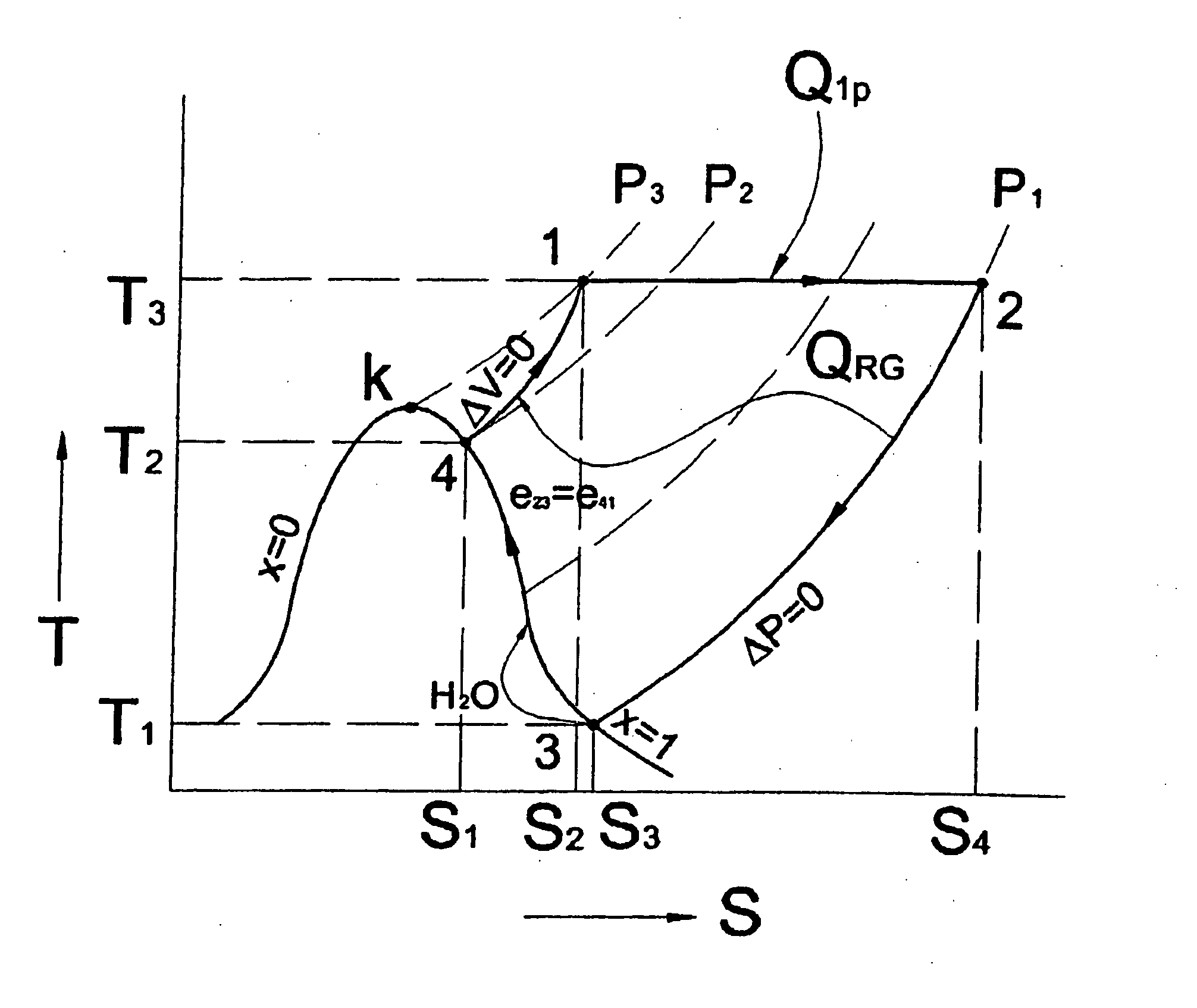
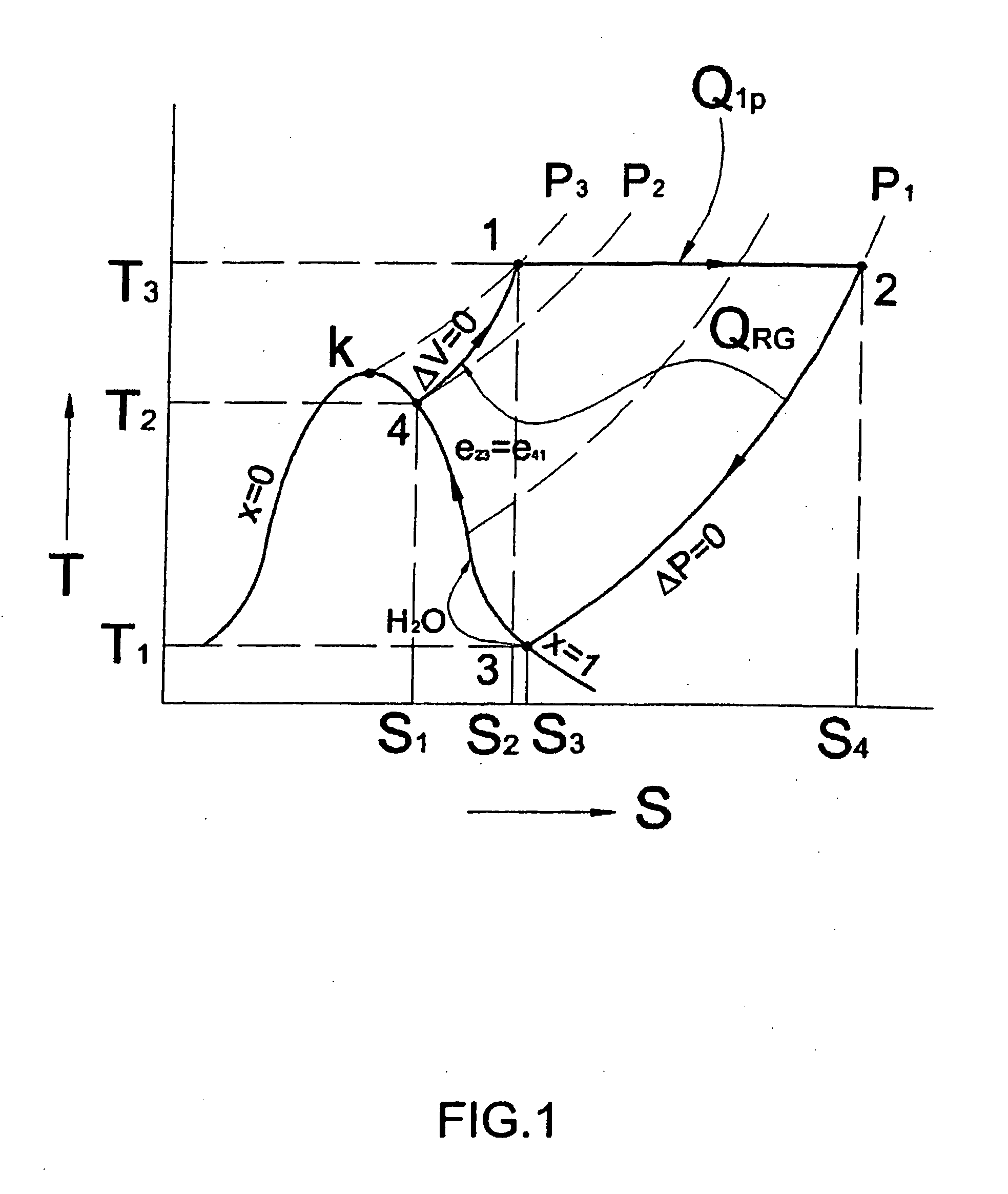
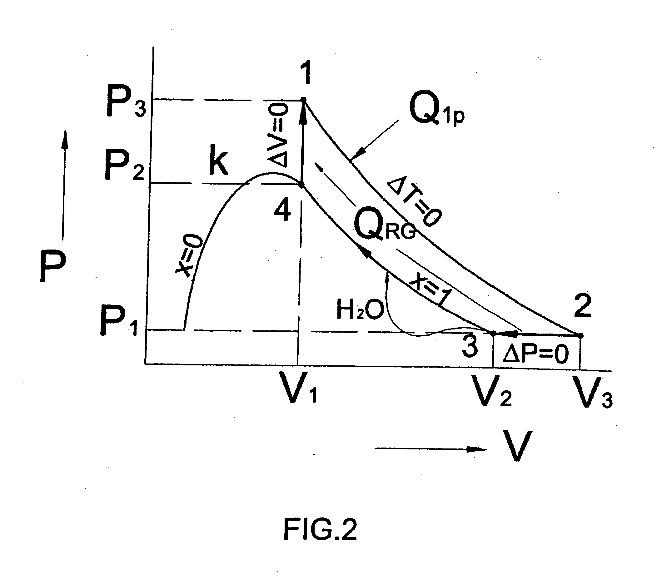
[0024] Reference will now be made in detail to the principles of the invention by explaining the invention on the basis of a thermodynamic steam cycle process, examples of which are illustrated in the accompanying drawings. Examples, mentioned therein, are intended to explain the invention and not to limit the invention in any kind.

[0025] According to the invention and its embodiments, an initial flux of a dry saturated vaporous working substance may be created, which may perform a steam power cycle in a single phase area with no change of its aggregate state. At the stage of compression of vaporous working substance, some part of the working substance in liquid state may be additionally injected into a compression cavity, and which injected substance may completely evaporate in the compression cavity with heat removal of heating of the working substance under compression. The amount of the injected liquid working substance may advantageously be regulated at each instant of time su...


PUM


Abstract

The invention relates to a process for transforming energy into exergy by supplying heat to a vaporous working substance subjected to an expansion and compression cycle and by obtaining the exergy in the expansion stage of the cycle. The cycle is performed in a single phase area of the vaporous working substance and working substance in liquid state is supplied to the cycle during the compression stage.

Description


Claims


Application Information

Patent Timeline
Owner ELTHOM ENTERPRISES
Learn More