
Rotary valve in an internal combustion engine

a technology of internal combustion engine and rotary valve, which is applied in the direction of oscillatory slide valve, machine/engine, mechanical apparatus, etc., can solve the problems of reducing engine efficiency, reducing engine efficiency, and reducing engine efficiency, so as to improve volumetric and thermodynamic engine efficiency, increase output and fuel economy, and reduce emissions

Inactive Publication Date: 2010-11-30
MUTH BARRY A
View PDF7 Cites 13 Cited by
  • Summary
  • Abstract
  • Description
  • Claims
  • Application Information

AI Technical Summary

Benefits of technology

[0015]The Rotary Valve Engine (RVE) presented makes significant improvements in volumetric and thermodynamic engine efficiency to significantly increase output and fuel economy while reducing emissions. Thermodynamic efficiency is significantly improved by reducing the fuel energy losses of the two largest contributors to thermodynamic entropy. These contributors are combustion process irreversibility and heat transfer loss. In the preferred embodiment of the RVE, a single rotary valve serves four cylinders of a four cycle engine.
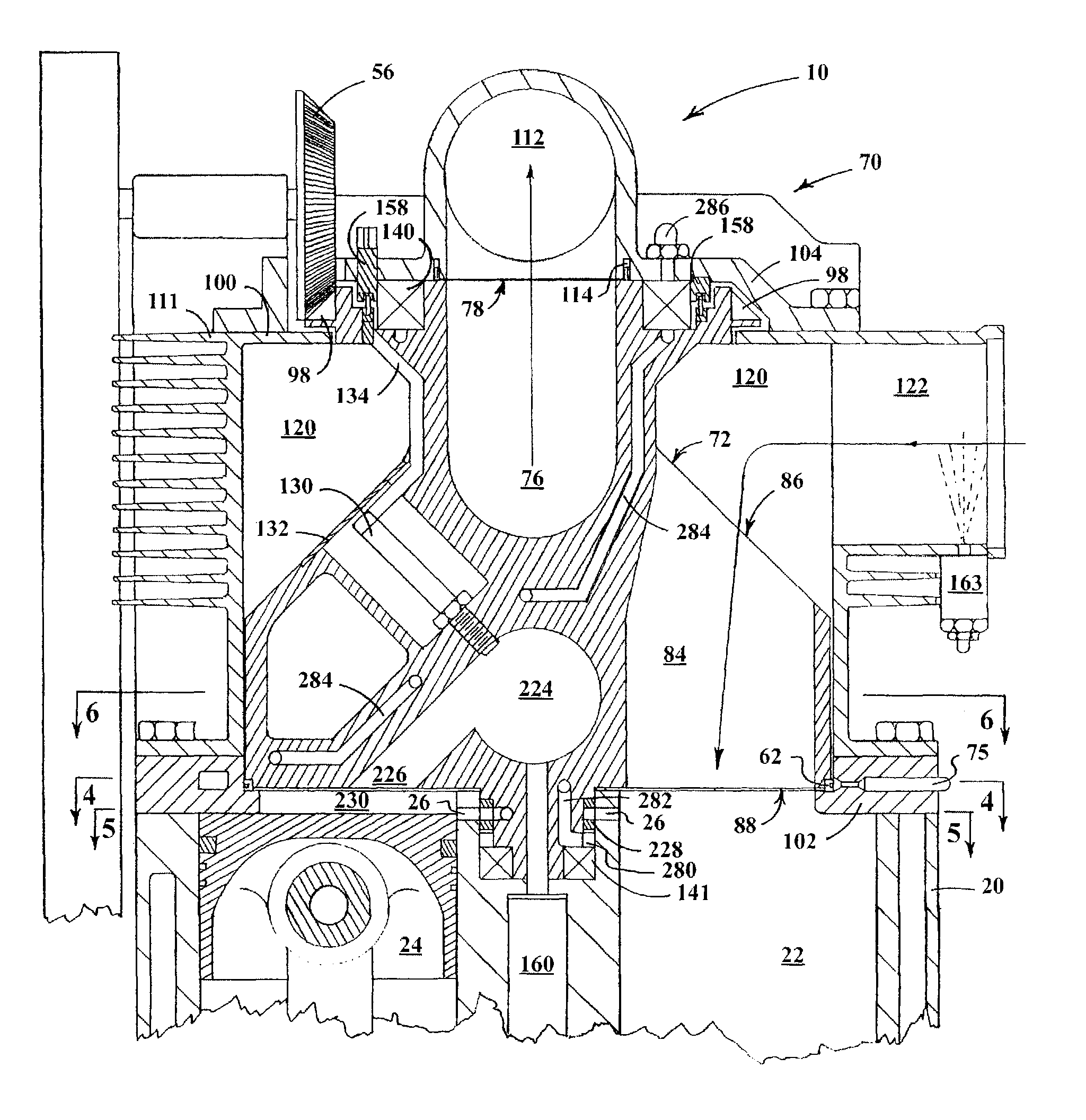
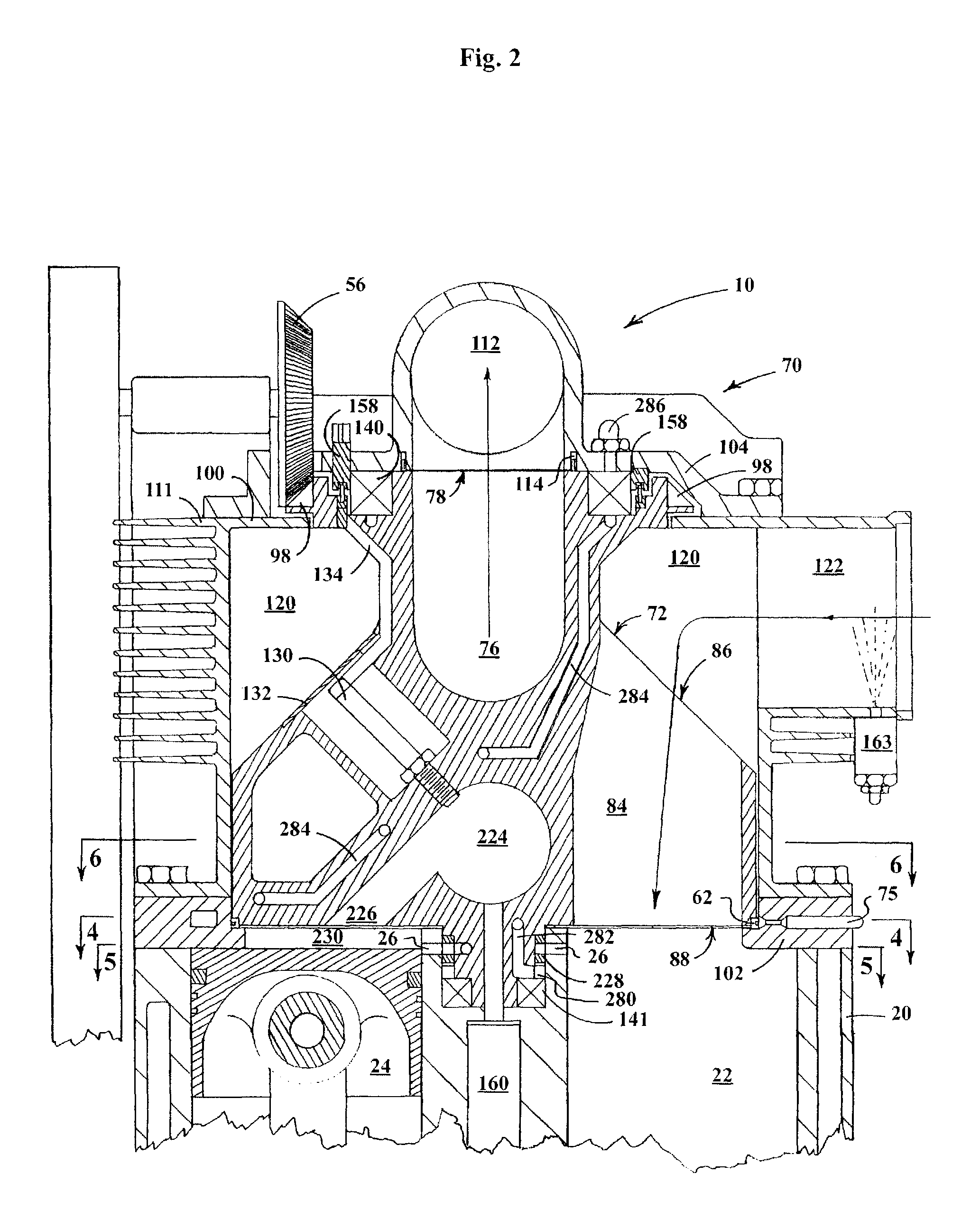
[0016]This art describes a novel combustion system to improve thermodynamic efficiency. First, the RVE has a conventional combustion chamber located in each cylinder head. However, this art utilizes a compound combustion system which adds a combustion chamber located in the rotary valve which serves all four cylinders. This stratified three stage combustion system starts the process by low pressure injection of fuel into the intake charge. Hot exhaust gas heats the intake charge as it passes through the intake passage by counterflow heat exchange. Another novel element, the variable compression valve, adds hot gas to the intake charge. The variable compression valve is an opening located in the shaft of the rotary valve which is opened and closed by an electronically controlled ring surrounding the rotary valve shaft. The variable compression valve transfers gas from the combustion cycle cylinder to the compression cycle cylinder to change the compression ratio, perform exhaust gas recirculation (EGR), and transport radical species. Stage one combustion ends with the compression of the charge to just under the ignition temperature. Stage two combustion starts with the opening of another novel element, the combustion valve. Also located in the rotary valve, the combustion valve operates similarly to the intake and exhaust valves allowing gas to sequentially enter from each cylinder in succession. A portion of the charge enters a passage which leads to the next novel element, the rotary valve combustion chamber (RVCC). The combustion valve is designed to access the RVCC late in the compression cycle and remains open during the combustion cycle. The RVCC is served by a single centrally located injector which injects fuel preheated by the block. As the piston continues to rise and push the charge from the head combustion chamber through the combustion valve, the added volume of the RVCC significantly reduces the rate of pressure rise of the charge decreasing the work done by the piston. To insure auto-ignition of the charge when the fuel is injected into the RVCC, the initial intake charge pressure is greatly increased. The increased charge pressure is generated by supercharging the intake charge and by increasing the compression ratio with the variable compression valve. As the charge enters the RVCC, it thoroughly and rapidly mixes with the injected fuel as it passes the RVCC injector to initiate combustion. Stage three of the combustion cycle begins with ignition of the head combustion chamber charge caused by the dramatically increased combustion chamber pressure due to ignition of the RVCC charge. At the conclusion of the combustion cycle, the combusted gases exit through a compounding element composed of angled or curved fins providing force against the rotary valve to increase output.

Problems solved by technology

These contributors are combustion process irreversibility and heat transfer loss.
However, the increased availability comes at the expense of increased work to compress the intake charge which reduces engine efficiency.
Currently, it is unclear whether either method has an efficiency advantage.

Method used


Image

  • Rotary valve in an internal combustion engine
  • Rotary valve in an internal combustion engine
  • Rotary valve in an internal combustion engine

Examples


Embodiment Construction

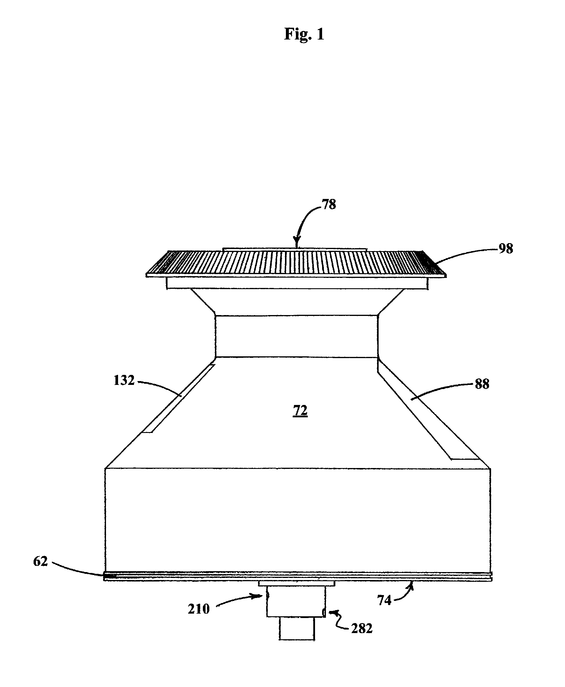
[0061]Referring now to the drawings, the preferred embodiment of the rotary valve engine of the present invention is shown therein and indicated generally by the numeral 10. The rotary valve engine 10 includes an engine block 20 having a plurality of cylinders 22 in which reciprocating pistons 24 are mounted. A rotary valve assembly 70 is disposed on the top of the engine block 20 for directing air into cylinders 22 and exhausting combustion gases. The rotary valve assembly 70 comprises a valve housing 100, a single disc-type rotary valve 72, and rotary valve bearing housing 104 for each group of cylinders. The engine block 20 encloses cylinders 22 which are circumferentially spaced about the axis of rotation of rotary valve 72. The center of each cylinder 22 is equidistant from the rotational axis of rotary valve 72. A piston 24 is mounted for reciprocating movement within each cylinder 22. Each piston 24 is connected by a piston rod 38 to a rotating crankshaft 40. Two parallel cra...


PUM


Abstract

A rotary valve engine using a single rotary valve serving multiple cylinders significantly increases both volumetric and thermodynamic efficiencies. A novel stratified three stage low temperature combustion system reduces both heat transfer loss and combustion process irreversibility. Using large intake and exhaust valves and passages to reduce throttling losses, the rotary valve also contains a combustion valve and passage connected to a central combustion chamber. Combustion is initiated for all cylinders by a fuel injector in this central chamber which then sequentially ignites a second combustion chamber charge located in each cylinder head. A passage in the rotary valve shaft transfers gas from the combustion cycle to the compression cycle varying the compression ratio of the engine, producing EGR, and transferring radical species for combustion to the next cycle. A compounding element on the rotary valve extracts additional thermal energy derived from reduced heat transfer loss and increased energy.

Description

FIELD OF THE INVENTION[0001]The present invention relates generally to internal combustion engines, and more particularly, to an internal combustion engine utilizing a rotary valve for directing the flow of intake air into the cylinders and exhausting gases from the cylinders.BACKGROUND OF THE INVENTION[0002]Currently, the most widely used engines are the Diesel and Otto spark ignited (SI) engines. While these engines offer remarkable performance at a relatively low cost, their basic design of over one hundred years ago is in need of serious improvement in the areas of thermal and pumping efficiency, emissions, and fuel economy. Refinement of the design of both engine types has improved the performance of these engines in recent decades. However, major improvements in the future are unlikely as this mature design is restricted by basic design limitations.[0003]One serious limitation is the volume of air which can be pumped through the engine. Pumping volume has historically been inc...

Claims


Application Information

Patent Timeline
Patent Type & Authority Patents(United States)
IPC IPC(8): F02B75/20F01L7/08
CPCF01L7/08F01L2101/02F01L2301/02
Inventor MUTH, BARRY A.
Owner MUTH BARRY A
Learn More