Internal-Combustion Engine With Guided Roller Piston Drive

a technology of internal combustion engine and piston drive, which is applied in the direction of positive displacement engine, bearing, shaft and bearing, etc., can solve the problems of unquestionable loss of thermodynamic efficiency of the actual work cycle of the engine relative to the efficiency of an ideal thermodynamic cycle, and unfavorable internal combustion engine. , to achieve the effect of improving reciprocating operation, high specific power, and high thermal and mechanical efficiency

Inactive Publication Date: 2008-05-29
KEY PARTNER HLDG
View PDF7 Cites 13 Cited by
  • Summary
  • Abstract
  • Description
  • Claims
  • Application Information

AI Technical Summary

Benefits of technology

[0019]The aim of the present invention is to eliminate in the best possible manner the drawbacks of known engines, by providing an internal-combustion engine with improved reciprocating operation, which can operate with any fuel, has higher thermal and mechanical efficiency, delivers a higher specific power for an equal displacement and rpm rate, and can achieve a higher rotation rate of the piston (or pistons) as a function of the system used even with respect to the engine shaft.
[0020]An object of the present invention is to provide an engine in which the masses that perform reciprocating and rotary motions have a low value in terms of friction and lateral thrusts in order to avoid stress affecting the pistons.
[0021]An object of the invention is in fact to eliminate these abnormal thrusts, thus recovering all the energy dissipations absorbed in known engines, utilizing all the power that can be delivered and further avoiding wear and ovalization of the cylinders and pistons as well as all mechanical noise.
[0022]Another object of the present invention is also to provide an internal-combustion engine with improved reciprocating operation which allows to improve the thermodynamic efficiency of the work cycle by obtaining a controlled and adjustable combustion at constant volume, such as the one predicted ideally by the Otto cycle and never provided anywhere in the world before now, with the goal of reducing specific fuel consumption and of yielding, for an equal amount of aspirated fluid, at least twice the power for an equal displacement and rpm rate, always with the possibility to control and modify the duration of the step of combustion at constant volume, thus reducing a good fraction (50% and more) of polluting emissions.
[0023]Other objects of the present invention consist in increasing the ratio between power output and engine weight and between power output and engine size; in simplifying the elements for transmitting the power transmitted to the engine shaft, facilitating the engine-gearbox coupling, at least halving the rpm rate of the engine shaft with respect to the rpm rate of the piston, further achieving a considerable reduction of the imbalances and consequent vibrations of reciprocating masses, thus achieving particularly high maximum torque values at low rpm rates.

Problems solved by technology

Part of the loss of thermodynamic efficiency of the actual work cycle of an engine with respect to the efficiency of an ideal thermodynamic cycle is unquestionably due to the way in which the combustion process occurs and to the connections of the pusher linkage system, i.e., to thermodynamic and mechanical efficiency.
These rotating bodies have been conceived in a plurality of versions by various designers and with two or more lobes, but the prototypes that have been produced have not yielded the expected results and therefore have been abandoned.
These known types of internal-combustion engine with reciprocating operation, in particular with a connecting rod-and-crank mechanism, have some important drawbacks which are due to an inflexible method of operation, which up to now it has not been possible to avoid.
These engines in fact have much lower thermodynamic efficiencies than the ideal ones predicted by Otto and absolutely do not allow constant-volume combustion, with the consequent drawback of having to use large quantities of fuel in order to obtain limited amounts of power.
This leads to high specific consumptions in order to deliver low power levels, differently from ideal engines with constant-volume combustion.
A further drawback of known engines is that when the respective pistons move from the top dead center to the bottom dead center and vice versa, lateral thrusts are discharged onto them (and therefore onto the entire mechanism) and absorb considerable energy and produce deformations on the cylinders and pistons, generating wear and noise of the mechanical type (so-called “piston slap”), shortening and also worsening the performance and life of said engines.

Method used


Image

  • Internal-Combustion Engine With Guided Roller Piston Drive
  • Internal-Combustion Engine With Guided Roller Piston Drive
  • Internal-Combustion Engine With Guided Roller Piston Drive

Examples


first embodiment

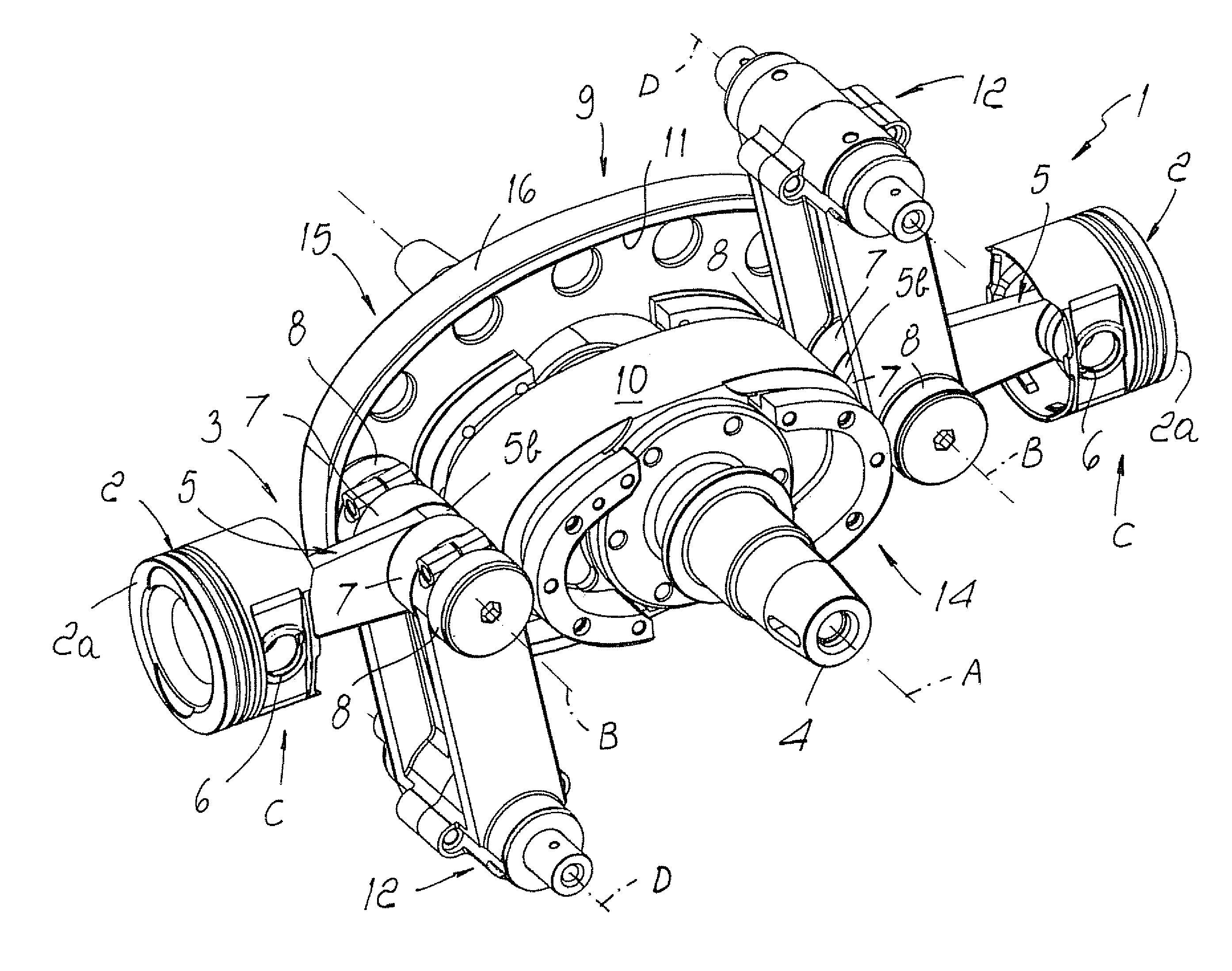
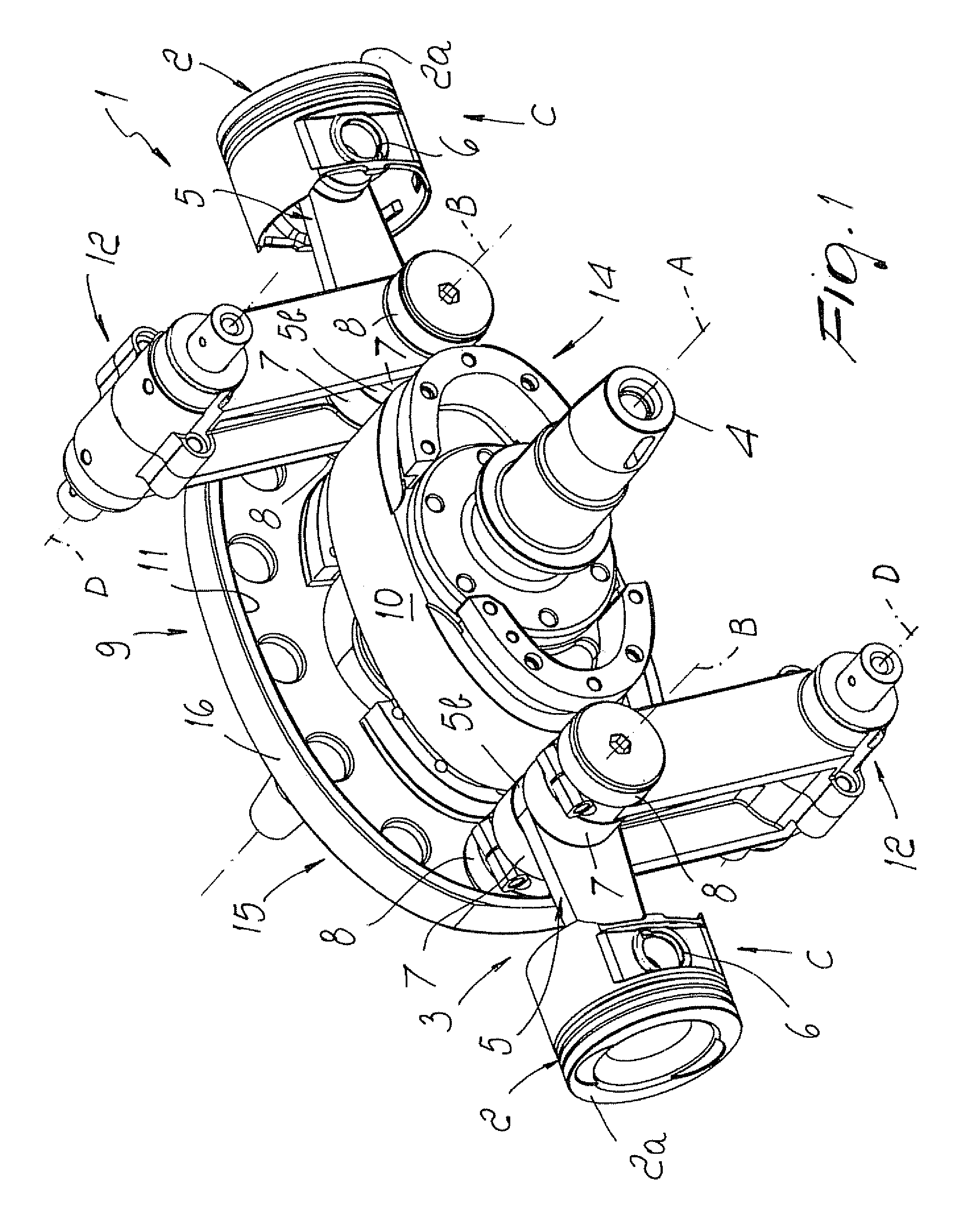
[0063]Again with reference to the engine 1, the rotating contoured body 9 (FIG. 2) comprises a body 14, on the outer perimetric surface of which the pusher circuit 10 is provided, and two coupled bodies 15, which are substantially parallel thereto and are rigidly associated with its opposite faces.

[0064]A respective track 16 is formed in relief on the faces of the coupled bodies 15 that are directed toward the body 14, and its internal profile forms a return circuit 11.

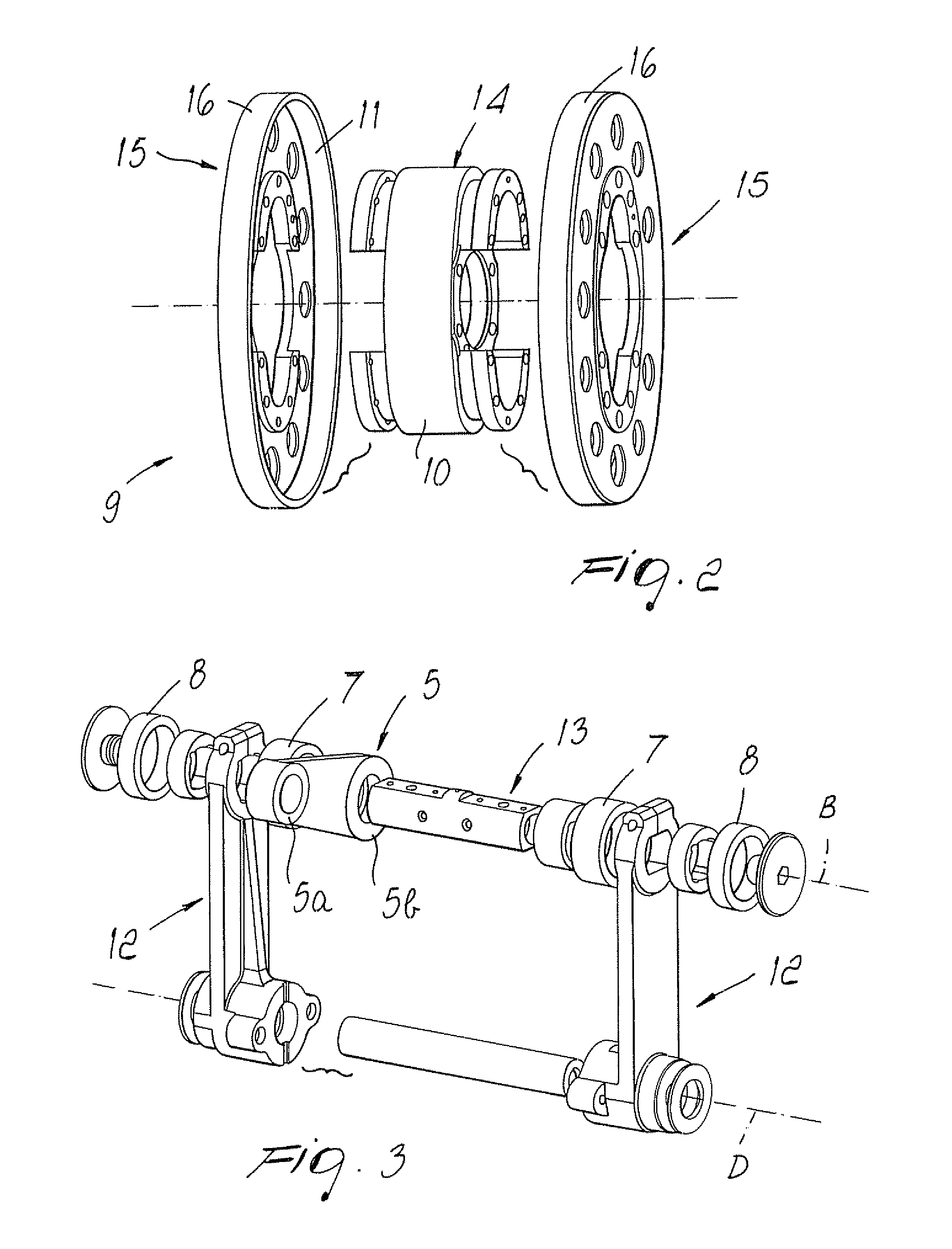
[0065]In the alternative embodiment, shown in FIGS. 6 and 7, the second end 5b of the push rod 5 is fork-shaped, each prong being provided with a respective eye, which supports a respective supporting shaft 13; the two supporting shafts 13 are mutually coaxial.

[0066]A respective pusher roller 7 and a respective return roller 8 are mounted on each of the two pins 13; in the sequence of the pusher rollers 7 and of the return rollers 8, the former are end rollers and the latter are interposed between them. In this case, ...

second embodiment

[0067]Again with reference to the engine 1, the rotating contoured body 9 can be constituted for example by a structural element 17, on each opposite face of which there are two circuit tracks in relief; a first circuit track 18 and a second circuit track 19, both of which are internal but on two different levels and are mutually concentric.

[0068]The profile of the two first internal circuit tracks defines the pusher circuit 10 and the profile of the two second internal circuit tracks defines the return circuit 11.

[0069]However, alternative embodiments are not excluded in which the number and arrangement of the pusher rollers 7 and of the return rollers 8 changes and accordingly the number and arrangement of the pusher circuits 10 and return circuits 11 changes, or in which the configuration of the push rod 5, of the guiding arms 12 and of the rotating contoured body 9 changes, each being possibly provided monolithically, in two or more parts, or in any other form that may allow to ...


PUM


Abstract

An internal-combustion engine (1) with improved reciprocating operation comprises at least one hollow cylinder (C), which contains a chamber for the evolution of a working fluid and has one end closed by a head and the opposite end closed by a piston (2) which can slide with a reciprocating rectilinear motion between a bottom dead center (BDC) and a top dead center (TDC), and a device (3) for converting the reciprocating rectilinear motion of the piston (2) into a rotary motion of an engine shaft (4) which comprises a push rod (5), which is substantially perpendicular to the engine shaft (4) and in which a first end (5a) is connected to the piston (2) and a second end (5b) is connected to at least one pin (13) for supporting at least one pusher roller (7) and at least one return roller (8), which rotate in mutually opposite directions, a rotating contoured body (9), which is fixed to the engine shaft (4) and is provided with at least one pusher circuit (10) and at least one return circuit (11), along which the respective rollers (8) travel, at least one guiding arm (12), in which one end is associated with the roller supporting pin (13) and the opposite end is articulated so that it can move about a fixed axis (D); the pusher and return circuits (10, 11) comprise respective circular arcs for the sliding of the pusher and return rollers (7, 8) which, when the piston (2) is proximate to the top dead center, are suitable to keep the push rod (5) and the piston (2) in a substantially stationary configuration over a predefined space or angle of rotation of the rotating contoured body, the volume of the chamber remaining substantially constant until explosion has occurred.

Description

TECHNICAL FIELD[0001]The present invention relates to an internal-combustion engine with improved reciprocating operation.BACKGROUND ART[0002]It is known that internal-combustion engines allow to convert the energy produced by the fuel into mechanical work by means of the working fluid inside the combustion chamber.[0003]Engines have a cyclic operation which comprises the steps of intake, compression, combustion or expansion, and discharge of the residual fluid in the form of unburned gases.[0004]The work cycles of known types of internal-combustion engine can be approximated by means of the Sabathé ideal thermodynamic cycle, which reproduces ideally the combustion process with two transformations: the first one at constant volume and the second one at constant pressure.[0005]The first two ideal thermodynamic cycles, which are simplifications of the Sabathé cycle, are known: the Otto cycle, in which combustion is represented by means of a constant-volume transformation, and the Dies...

Claims


Application Information

Patent Timeline
Patent Type & Authority Applications(United States)
IPC IPC(8): F02B75/24
CPCF01B1/0668F02B75/24F01B1/08F01B1/06F02B75/32
Inventor FANTUZZI, LUCIANO
Owner KEY PARTNER HLDG
Why Eureka
Try Eureka