Gas turbine engine anti-icing system

a technology for gas turbine engines and anti-icing, which is applied in the direction of engines, efficient propulsion technologies, machines/engines, etc., can solve the problems of reducing the aerodynamic performance of ess, damage to downstream components, and ess is prone to ice buildup in use, so as to increase the thermodynamic efficiency of the engine and achieve the effect of sufficient energy

Active Publication Date: 2018-04-17
ROLLS ROYCE PLC
View PDF16 Cites 12 Cited by
  • Summary
  • Abstract
  • Description
  • Claims
  • Application Information

AI Technical Summary

Benefits of technology

[0011]Advantageously, the heated bypass duct air from the environmental control system pre-cooler is used to provide heat to a further heat transfer medium, which is used to provide anti-icing air for the ESS. It has been surprisingly found that the heat rejected from the compressor bleed air to the bypass duct air during different stages of the aircraft flight cycle substantially matches the heat required to de-ice the ESS, and consequently, such an arrangement provides sufficient energy for ESS anti-icing under substantially all operating conditions. Consequently, the rejected heat from the pre-cooler can be used in ESS anti-icing, thereby increasing the thermodynamic efficiency of the engine.

Problems solved by technology

The ESS is prone to ice buildup in use due to the low temperatures sometimes experienced during engine operation, particularly at the leading edge.
Such ice can reduce the aerodynamic performance of the ESS, and / or cause damage to downstream components such as rotors of the compressors 14, 16 where large pieces of ice breakoff.
This results in additional electrical load on the engine generators, and hence increased fuel burn, as the engine must be operated at higher powers to provide sufficient torque to power the generators.
However, use of this compressed air is not thermodynamically efficient, since the compressed air is not utilised in the thermodynamic cycle of the engine 10.
Furthermore, large pipes are required to deliver this air to the ESS.
These pipes carry hot, high pressure air, and so must be relatively heavy to accommodate this.
The hot air also presents a fire risk should a leak occur.
Consequently, while this method may provide adequate de-icing, it also increases the weight, complexity and cost of the engine, while reducing fuel efficiency.

Method used


Image

  • Gas turbine engine anti-icing system
  • Gas turbine engine anti-icing system
  • Gas turbine engine anti-icing system

Examples


Embodiment Construction

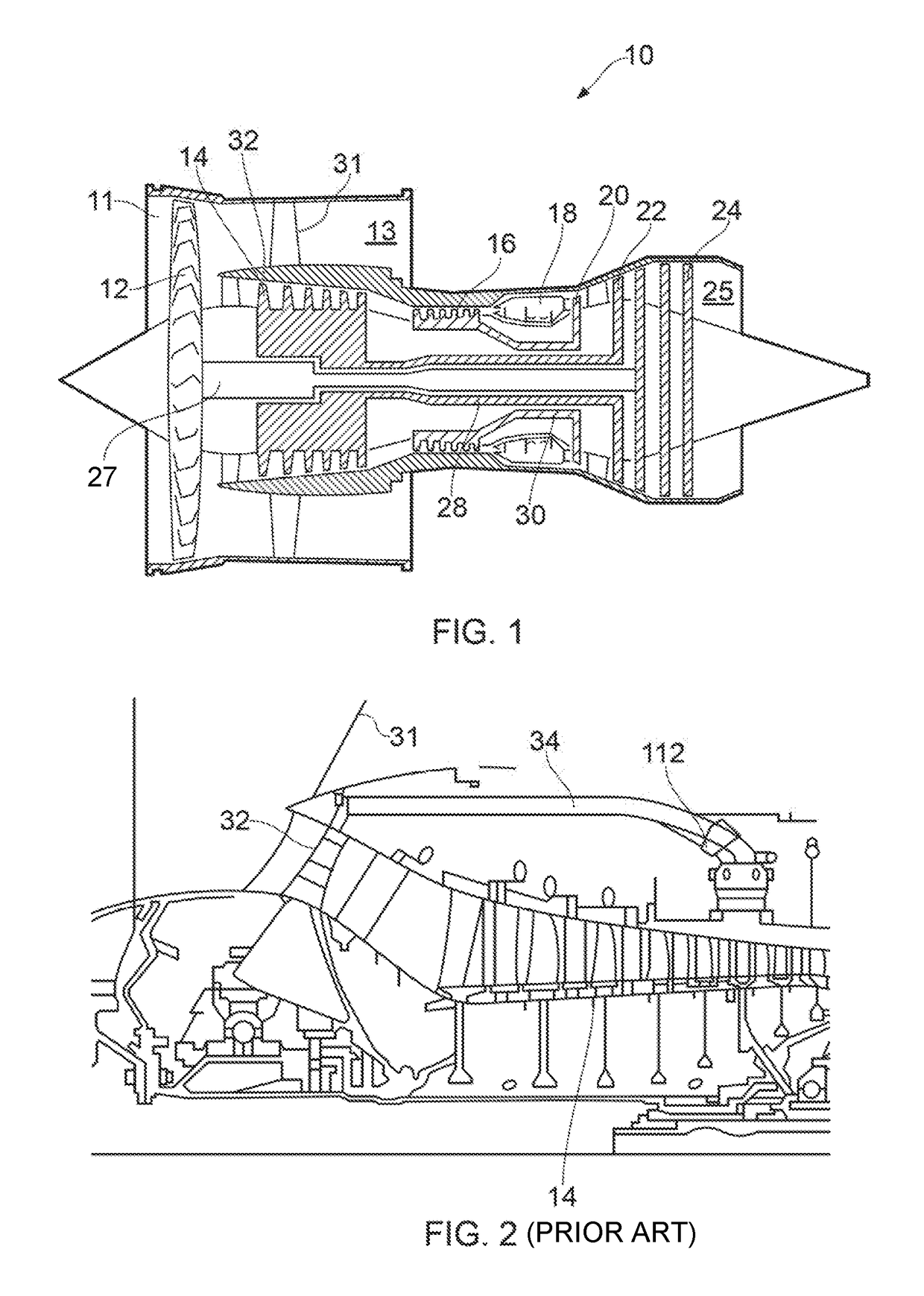
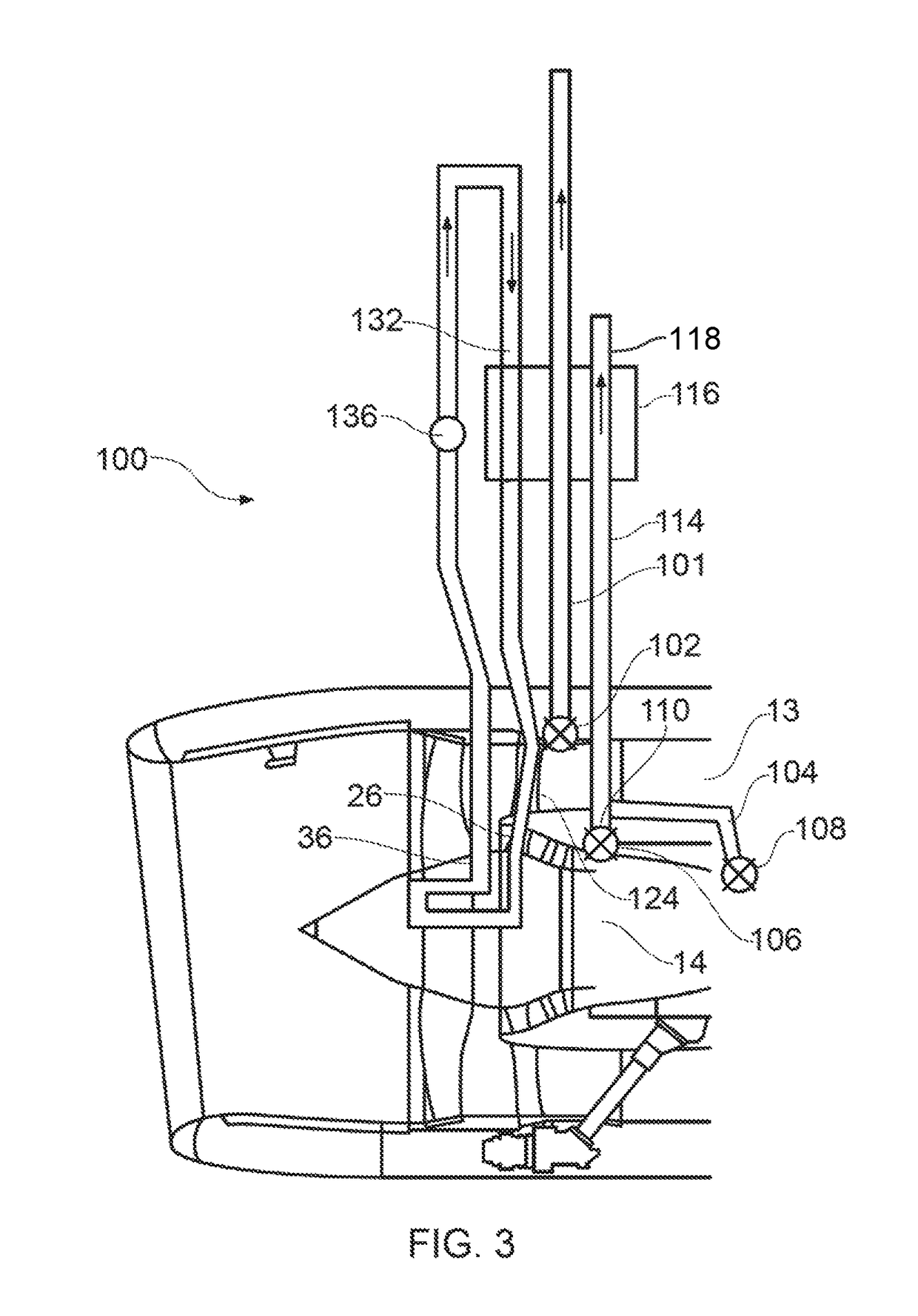
[0025]FIG. 3 shows a first anti-icing system 100 for use with a gas turbine engine such as engine 10 shown in FIG. 1. The system is shown schematically, and does not represent actual sizes and positions of components.

[0026]The system 100 comprises a bypass air passage 101 which is configured to receive cool air at slightly above ambient pressure from the bypass duct 13. The passage 101 includes a flow valve 102 at an inlet thereof, which regulates mass flow through the passage 101 in use in accordance with signals received from a controller such as FADEC (not shown).

[0027]High pressure and intermediate pressure compressor bleed passages 104, 106 are also provided, which provide high pressure air from the high pressure and intermediate pressure compressors 14, 16 respectively of engine 10. Valves 108, 110 are provided, to regulate mass flow through the respective passages 104, 106. Again, these valves 108, 110 are controlled by FADEC. Air from the high and intermediate pressure bleed...


PUM


Abstract

An anti-icing system for an engine section stator of a gas turbine engine. The system includes an environmental control system pre-cooler heat exchange system and a conduit. The environmental control system pre-cooler heat exchange system is configured to exchange heat between air bled from a compressor of the engine and bypass duct air. The conduit is configured to exchange heat from the pre-cooler heat exchange system to a heat transfer medium. The conduit is also configured to transfer the heat from the heat transfer medium to the engine section stator.

Description

FIELD OF THE INVENTION[0001]The present invention relates to an anti-icing system for removing and / or preventing the buildup of ice in a gas turbine engine.BACKGROUND TO THE INVENTION[0002]FIG. 1 shows a high-bypass gas turbine engine 10. The engine 10 comprises, in axial flow series, an air intake duct 11, an intake fan 12, a bypass duct 13, an intermediate pressure compressor 14, a high pressure compressor 16, a combustor 18, a high pressure turbine 20, an intermediate pressure turbine 22, a low pressure turbine 24 and an exhaust nozzle 25. The fan 12, compressors 14, 16 and turbines 20, 22, 24 all rotate about the major axis of the gas turbine engine 10 and so define the axial direction of gas turbine engine.[0003]Air is drawn through the air intake duct 11 by the intake fan 12 where it is accelerated. The accelerated air then passes through a plurality of Outlet Guide Vanes (OGVs) 31. A significant portion of the airflow is discharged through the bypass duct 13 generating a corr...

Claims


Application Information

Patent Timeline
Patent Type & Authority Patents(United States)
IPC IPC(8): F01D25/02F02C7/047F02K3/115F01D25/10F02C7/141F01D17/10F01D15/08F01D9/02B64D13/06
CPCF01D25/02F01D9/02F01D15/08F01D17/105F01D25/10F02C7/047F02K3/115F02C7/141Y02T50/675B64D2013/0607F05D2220/32F05D2240/10F05D2260/208Y02T50/60
Inventor APPUKUTTAN, AJITHKEELER, BENJAMINVANACORE, PAOLO
Owner ROLLS ROYCE PLC
Why Eureka
Try Eureka