Deep water installation vessel

a technology for installing vessels and deep water, which is applied in the field of deep water installation vessels, can solve the problems of limited space limited space, and danger to personnel working on the work deck, and achieves the effects of large deck space, convenient storage and movement, and convenient storag

Inactive Publication Date: 2007-08-23
SINGLE BUOY MOORINGS INC
View PDF12 Cites 14 Cited by
  • Summary
  • Abstract
  • Description
  • Claims
  • Application Information

AI Technical Summary

Benefits of technology

[0005]In accordance with one embodiment of the present invention, an installation vessel is provided that has an unusually large amount of deck space for a hull of given length and width, and that confines a dangerous area where there is rapid movement of elongated members along a deck and into or out of the sea, to a limited deck area. The installation vessel includes a hull and an upper working deck at the top that has a large flat deck area where material and equipment can be easily stored and moved around. The vessel also has a lower working deck that lies at least 1.8 meters

Problems solved by technology

The limited space on the work deck limits the amount of materials, equipment and tools that can be stowed.
The space is limited especially because space must be left between winches and a stern roller, between which elongated elements such as cables, chains and hoses are rapidly moved into or out of the sea.
The rapidly moved elongated elements create a danger to personnel

Method used


Image

  • Deep water installation vessel
  • Deep water installation vessel
  • Deep water installation vessel

Examples


Embodiment Construction

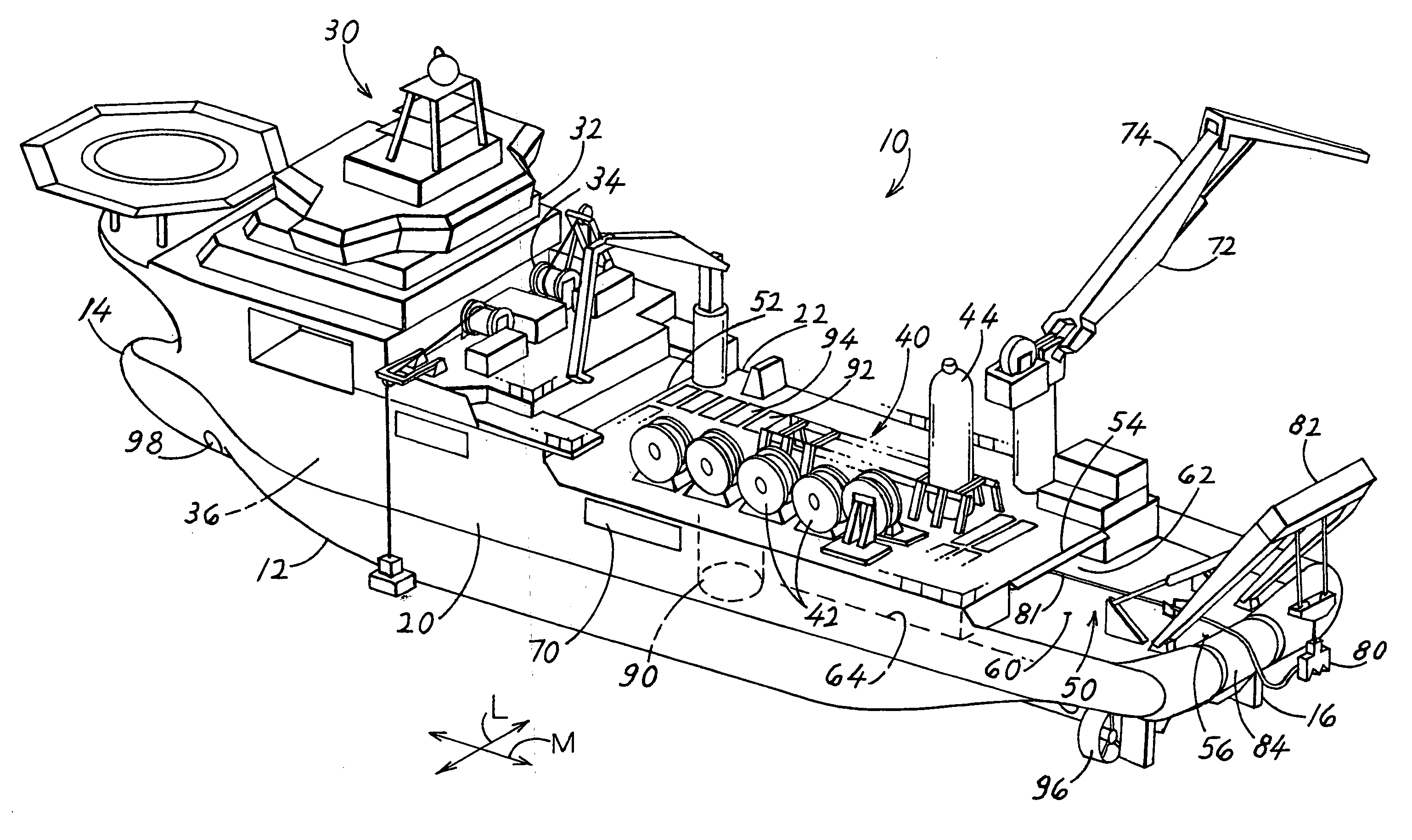
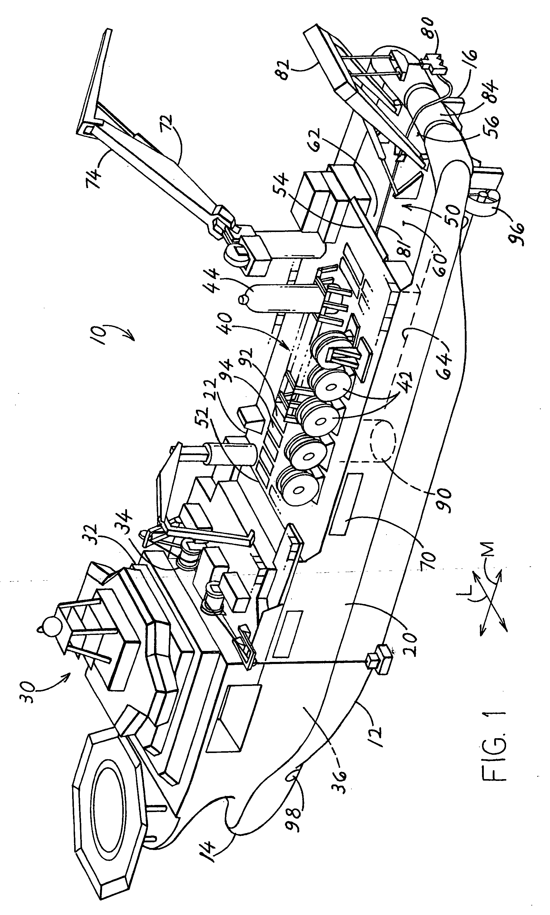
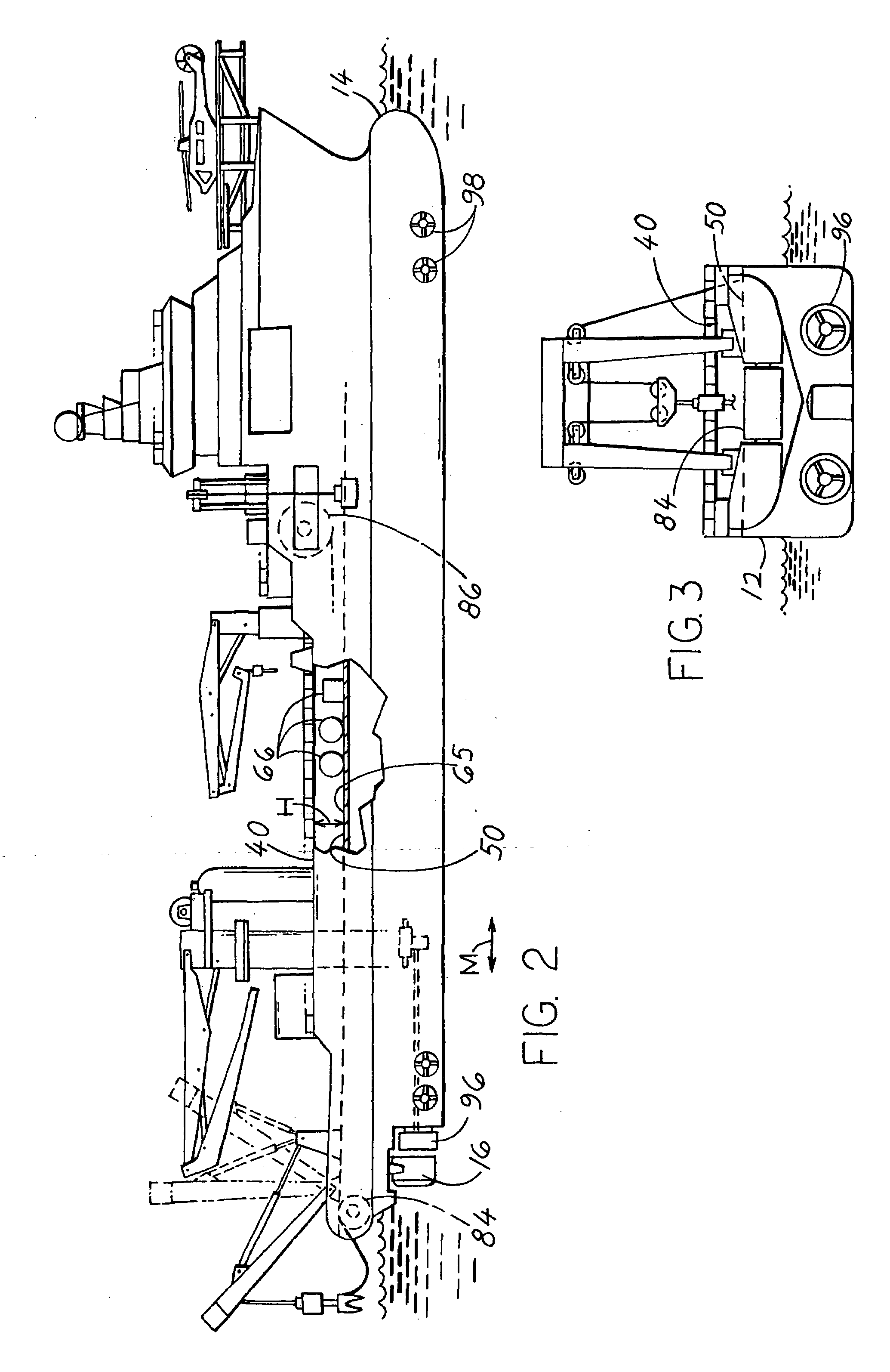
[0011]FIG. 1 illustrates an installation vessel 10 which includes a hull 12 having a bow 14, a stern 16, and port and starboard sides 20, 22 that form the periphery of the vessel. The front portion 30 of the vessel is occupied by a helicopter deck, a navigation bridge, control rooms and crew quarters, ROV (remotely operated vehicles), heavy duty winches 34 for ROV handling and control rooms for them, and other heavy equipment. Below-deck portions 36 of the vessel are occupied by fuel tanks, engines, chain lockers and other heavy equipment. All of the foregoing equipment is stored in the installation vessel when it is outfitted to ready it to sail what may be a long distance, to a mobilization harbor that is located near the site where the installation will occur. At the mobilization harbor, supplies that will be used up in the installation, and specialized installation equipment for the particular site, are loaded onto the vessel, and the vessel sails to the installation site. The i...


PUM


Abstract

An installation vessel has upper and lower decks (40, 50) that are vertically spaced about 3 meters apart, with most of the lower deck covered by the upper one, but with a rear portion (60) of the lower deck being uncovered. The upper deck is used primarily for storage, while the lower deck is the one used for installation of anchor chains, wires, ropes, etc. that pass from a winch (81) to a stern roller (84) at the rear of the lower deck, so dangerous conditions of chains, wires, ropes, etc. moving along a deck during installation are confined to the lower deck. A main crane (72) that lies on one side of the vessel, lies forward of the rear end of the upper deck at a location wherein the crane can reach all portions of the uncovered lower deck portion and most of the upper deck.

Description

[0001]Applicant claims priority from U.S. provisional patent application Ser. No. 60 / 774,285 filed Feb. 17, 2006.BACKGROUND OF THE INVENTION[0002]Installation vessels are used to install items during the setup of a hydrocarbon production system that produces hydrocarbons from the sea floor, a system where hydrocarbons are transferred to or from a shore-based installation, and other offshore systems especially for hydrocarbon transfer and well maintenance. These include installations where a floating body is held by chains extending from a turret or by spread mooring. The installation vessel installs items on the sea floor, including anchors, piles, manifolds, subsea trees (wellheads), templates and pumps, items that are to lie at a height between the sea floor and the sea surface such as buoyancy tanks that are to be attached to risers, and other in-sea items or tools including cables, chains, and underwater hammers. A conventional installation vessel has a single work deck extendin...

Claims


Application Information

Patent Timeline
IPC IPC(8): B63B9/06
CPCB63B35/00B63B21/50B63B2003/147B63B3/48
Inventor SEBELLIN, ERIC
Owner SINGLE BUOY MOORINGS INC
Why Eureka
Try Eureka