Solar-powered desalination system

a desalination system and solar energy technology, applied in the field of solar energy desalination system, can solve problems such as system complexity, and achieve the effects of efficient desalination water, efficient use of heat supplied, and elimination of excessive number of pumps

Inactive Publication Date: 2007-08-23
PRUEITT MELVIN L
View PDF14 Cites 28 Cited by
  • Summary
  • Abstract
  • Description
  • Claims
  • Application Information

AI Technical Summary

Benefits of technology

The invention aims to use heat efficiently to desalinate seawater or other aqueous solutions by using the same heat multiple times at sequentially lower temperatures. It also aims to eliminate excessive pumps while desalinating water efficiently. The invention provides a compact desalination unit with closely spaced parallel plates that separate the desalination chambers. Additionally, it provides a means of removing entrapped air in the water vapor without having to deaerate the saline water before introducing it into the desalination unit.

Problems solved by technology

The technical problem addressed in this patent is how to improve the efficiency of desaling devices that use multiple plates with small chambers between them. Currently, these designs have issues with wasted heat from the initial stages and excessive noise caused by air bubbles. Additionally, they require high-powered pumps for efficient operation.

Method used


Image

  • Solar-powered desalination system
  • Solar-powered desalination system
  • Solar-powered desalination system

Examples


Embodiment Construction

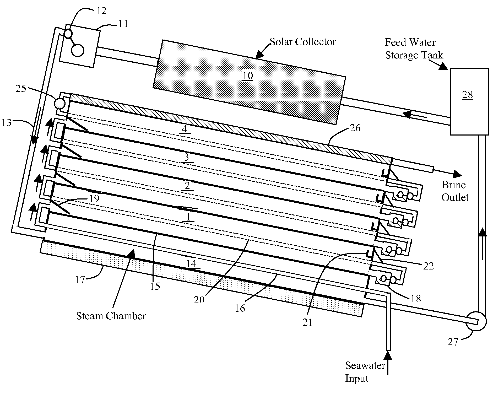
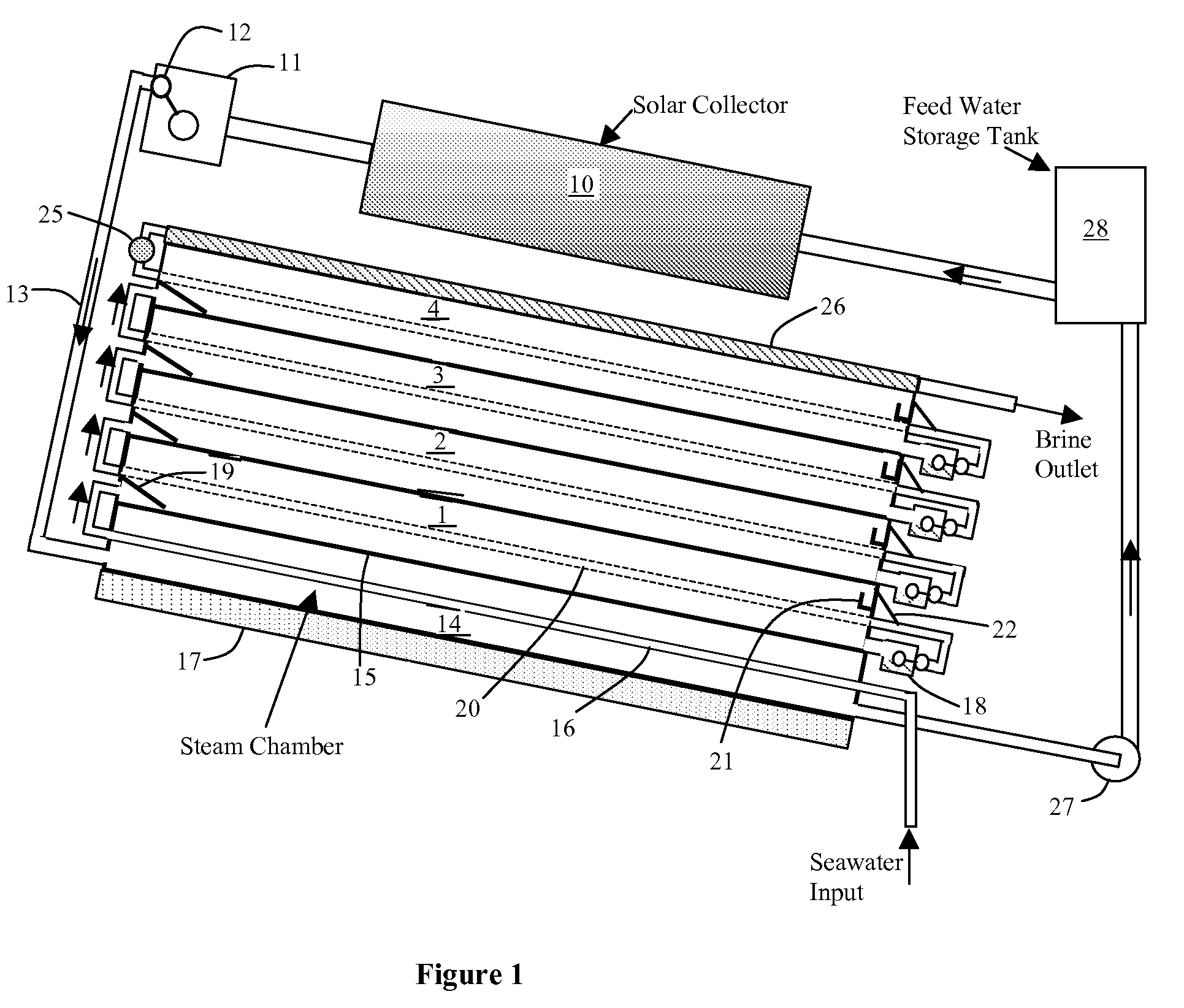
[0024]FIG. 1 shows a schematic of this embodiment of SunDesal. For small systems, the solar collector could be a solar trough or even a flat solar collector. For large desalination plants, solar trough collectors or a conical collector called “Suncone” can be used to generate steam. For conditions in which the water does not reach the boiling point (100° C.), steam can still be generated at lower temperatures by lowering the pressure.

[0025]The SunDesal unit consists of a number of flat plates that separate the stages of the unit. The first stage (bottom stage) is the hottest, and each stage above that is progressively cooler. The top stage is cooled by evaporation of water that flows down the evaporation tray, or it can be cooled by cold water flow.

[0026]In FIG. 1, heat is collected by the solar collector 10. A steam control unit 11 has a float valve 12, which prevents the heated fluid from going to the desalination unit until the fluid becomes vapor. That is, at startup, the solar ...


PUM

PropertyMeasurementUnit
Temperatureaaaaaaaaaa
Hygroscopicityaaaaaaaaaa
Pressureaaaaaaaaaa

Abstract

This invention has a series of multiple parallel plates that form desalination chambers between them that have seawater or other saline water flowing down the inside of one plate of each chamber. Steam which is generated by solar heat or other heat source condenses on the outside of first chamber of the series on the plate, which has seawater running down it. This releases heat that evaporates the seawater. The vapor flows to the other wall (plate) of the desalination chamber and condenses, and this releases heat that flows through the plate to the next stage of parallel plates and evaporates seawater flowing down the other side of the plate. Each succeeding stage operates at a lower temperature than the previous stage. The final stage is cooled by the evaporation of seawater into the air. One embodiment of the invention has the parallel plates sloped at an angle to the horizontal so that the seawater flows down on the lower plate and evaporates with heat supplied from below. The vapor condenses on the ceiling of the chamber. Since each succeeding stage upward is at a lower temperature, the vapor pressure will be lower in succeeding stages. This pressure differential can be used to pump the seawater from one stage to the next higher stage.

Description


Claims


Application Information

Patent Timeline
Owner PRUEITT MELVIN L
Why Eureka
Try Eureka