

Vibrator
a vibrator and frequency field technology, applied in the field of vibrators, can solve the problems of inability to obtain a sufficient vibration amplitude to surely indicate an incoming call to the user, and the frequency of the input signal may not fall within the resonance frequency region t of the vibrator,
- Summary
- Abstract
- Description
- Claims
- Application Information
AI Technical Summary
Benefits of technology
Problems solved by technology
Method used
Image

Examples
first embodiment
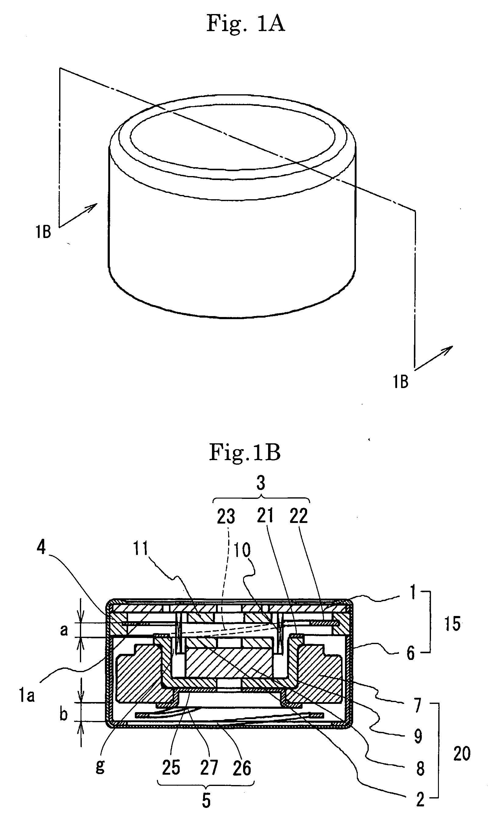
[0035]A vibrator according to the present invention has, as shown in FIG. 1B, a cylindrical voice coil 10, a vibrating member 20, and a first and a second suspensions 3 and 5 that resiliently support the vibrating member 20. When the voice coil 10 is supplied with an alternating current, the vibrating member 20 is reciprocated in the axial direction of the voice coil 10, thereby generating vibrations. The voice coil 10, the vibrating member 20, and the first and the second suspensions 3 and 5 are housed in a casing 15. The casing 15 is formed from a cup-shaped member 6 that is coaxial with respect to the voice coil 10. The casing 15 further has a circular base plate 1 that closes the opening of the cup-shaped member 6 and that supports the voice coil 10. The base plate 1 has wiring for supplying an input signal to the voice coil 10. The vibrating member 20 has a cup-shaped yoke 9 placed coaxially with respect to the voice coil 10. A magnet 8 and a top plate 2 are successively stacke...
second embodiment
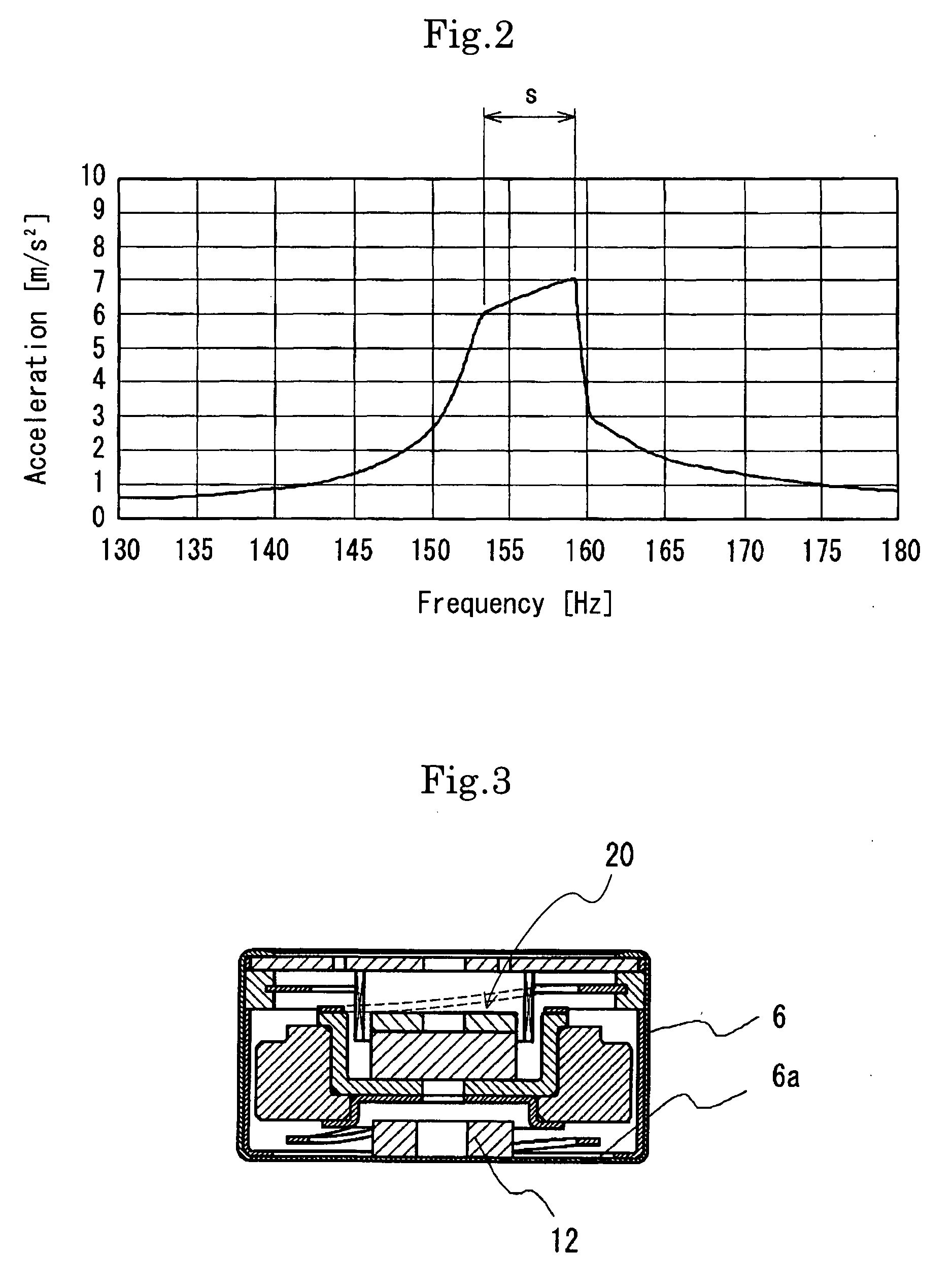
[0041]FIG. 3 shows a vibrator according to the present invention. In this vibrator, as shown in the figure, a buffering member 12 formed from “Poron”, which is a microcellular polymer foam, is provided on the upper surface (surface facing the vibrating member 20) 6a of the bottom wall of the cup-shaped member 6 of the casing 15.
[0042]FIG. 4 shows a vibrator according to a third embodiment of the present invention. In this vibrator, as shown in the figure, a buffering member 11 made from “Poron”, which is a microcellular polymer foam, is provided on the lower surface 1a of the base plate 1. In addition, a buffering member 12 made from “Poron”, which is a microcellular polymer foam, is provided on the upper surface 6a of the bottom wall of the cup-shaped member 6. The vibrator of this embodiment offers the same advantageous effects as those obtained from the vibrator of the first embodiment. It should be noted, however, that the vibrator of the first embodiment is preferable because i...
fourth embodiment
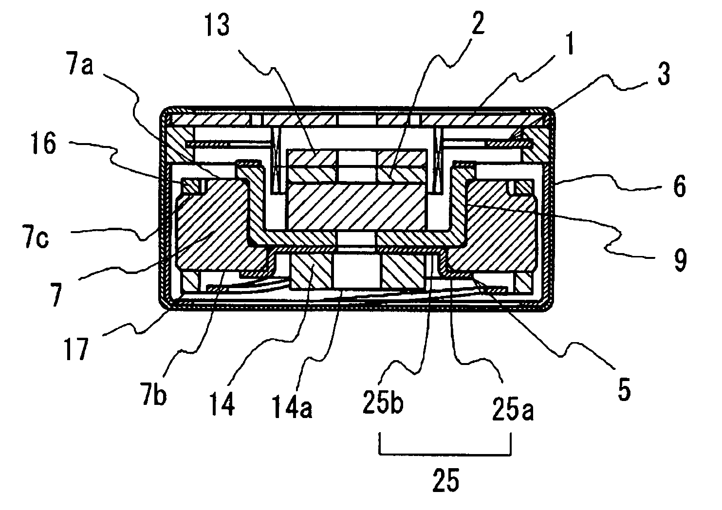
[0043]FIG. 5 shows a vibrator according to the present invention. In this vibrator, as shown in the figure, a buffering member 13 made from “Poron”, which is a microcellular polymer foam, is provided on the upper surface (surface facing the base plate 1) of the top plate 2, and a buffering member 12 made from “Poron” is provided on the bottom wall 6a of the cup-shaped member 6. In addition, ring-shaped buffering members 16 and 17 are provided on the weight 7, which is secured to the yoke 9. The upper surface of the buffering member 16 provided on the weight 7 is substantially flush with the upper surface 7a of the weight 7. The buffering member 17 is positioned on the lower surface 7b of the weight 7 so as to face the bottom wall of the casing 15. The buffering member 17 has an inner diameter with which it will not interfere with the second suspension 5.
PUM
 Abstract
Description
Claims
Application Information