
System and method for supervising battery for vehicle

a vehicle and battery technology, applied in the direction of electric devices, safety/protection circuits, instruments, etc., can solve the problems of user discomfort, battery may finally run out, and the operation of the electrical unit consumes the battery on the vehicle, so as to reduce the power of the battery

Inactive Publication Date: 2007-08-23
FUJITSU GENERAL LTD
View PDF9 Cites 15 Cited by
  • Summary
  • Abstract
  • Description
  • Claims
  • Application Information

AI Technical Summary

Benefits of technology

[0006]The present invention has been made in view of the above circumstances, and provides a system and a method for supervising a battery for a vehicle in which electrical unit on the vehicle consumes a reduced amount of battery power while conformability of users is improved.
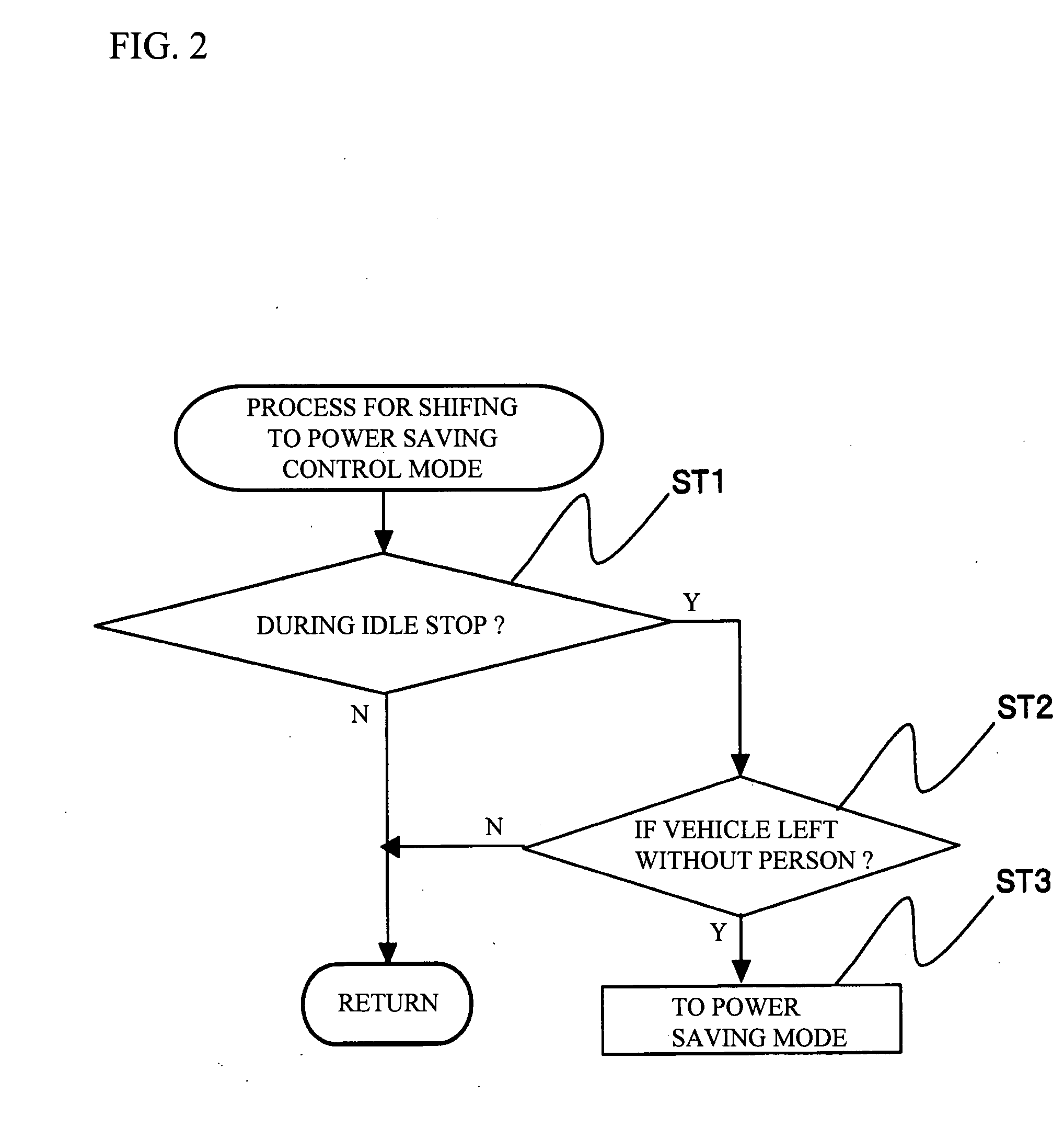
[0007]According to an aspect of the present invention, there is provided a system for supervising a battery mounted on a vehicle, the system including: a first part that detects a person in a vehicle in a stopped state; and a second part that executes a power saving control for reducing power of a battery on the vehicle consumed in electrical units mounted on the vehicle when the first part detects no person in the vehicle. It is thus possible to prevent battery power from being wastefully consumed when no person is in the vehicle.
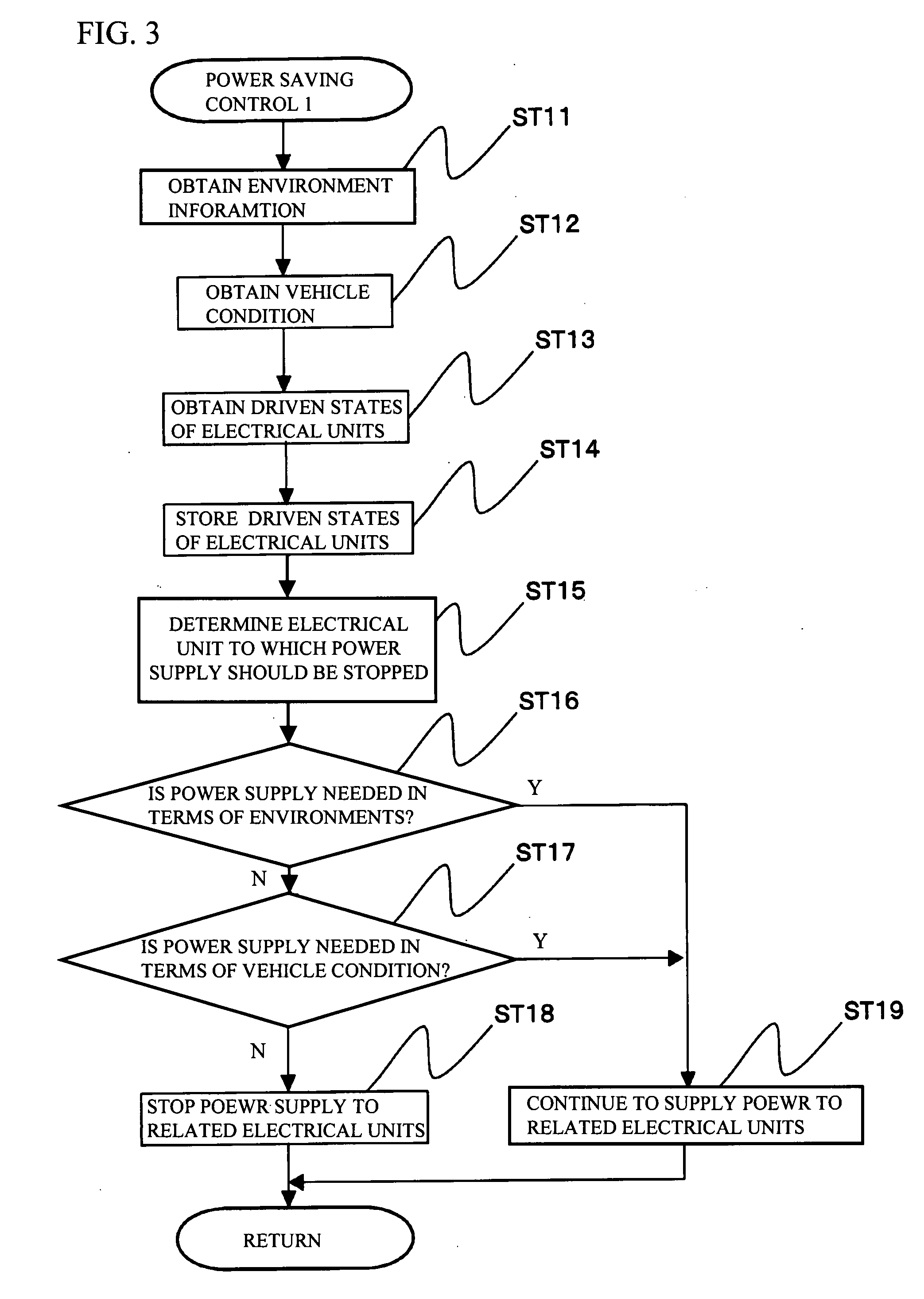
[0008]The system may be configured so that the second part determines to which electrical units the power saving control should be executed on the basis of at least one of states of the electrical units, environment about the vehicle, and a vehicle condition. It is thus possible to reduce battery power consumption while preventing a specific electrical unit important to the driver or passenger in the stopped state from being stopped. It is also possible to appropriately select electrical units to which the power saving control should be carried out because at least one of the states of the electrical units, the environment about the vehicle, and the vehicle condition is taken into consideration.

Problems solved by technology

In this case, if the user goes out of the vehicle while an electrical unit such as an air conditioner, a navigation system or an audio system is operating, the operating electrical unit consumes a battery on the vehicle, and the battery may finally run out.
On the other hand, the user may feel uncomfortable if all electrical units are OFF when the user returns to the vehicle or the user is needed to operate the ignition key to restart the engine.

Method used


Image

  • System and method for supervising battery for vehicle
  • System and method for supervising battery for vehicle
  • System and method for supervising battery for vehicle

Examples


Embodiment Construction

[0020]A description will now be given, with reference to the accompanying drawings, of embodiments of the present invention.

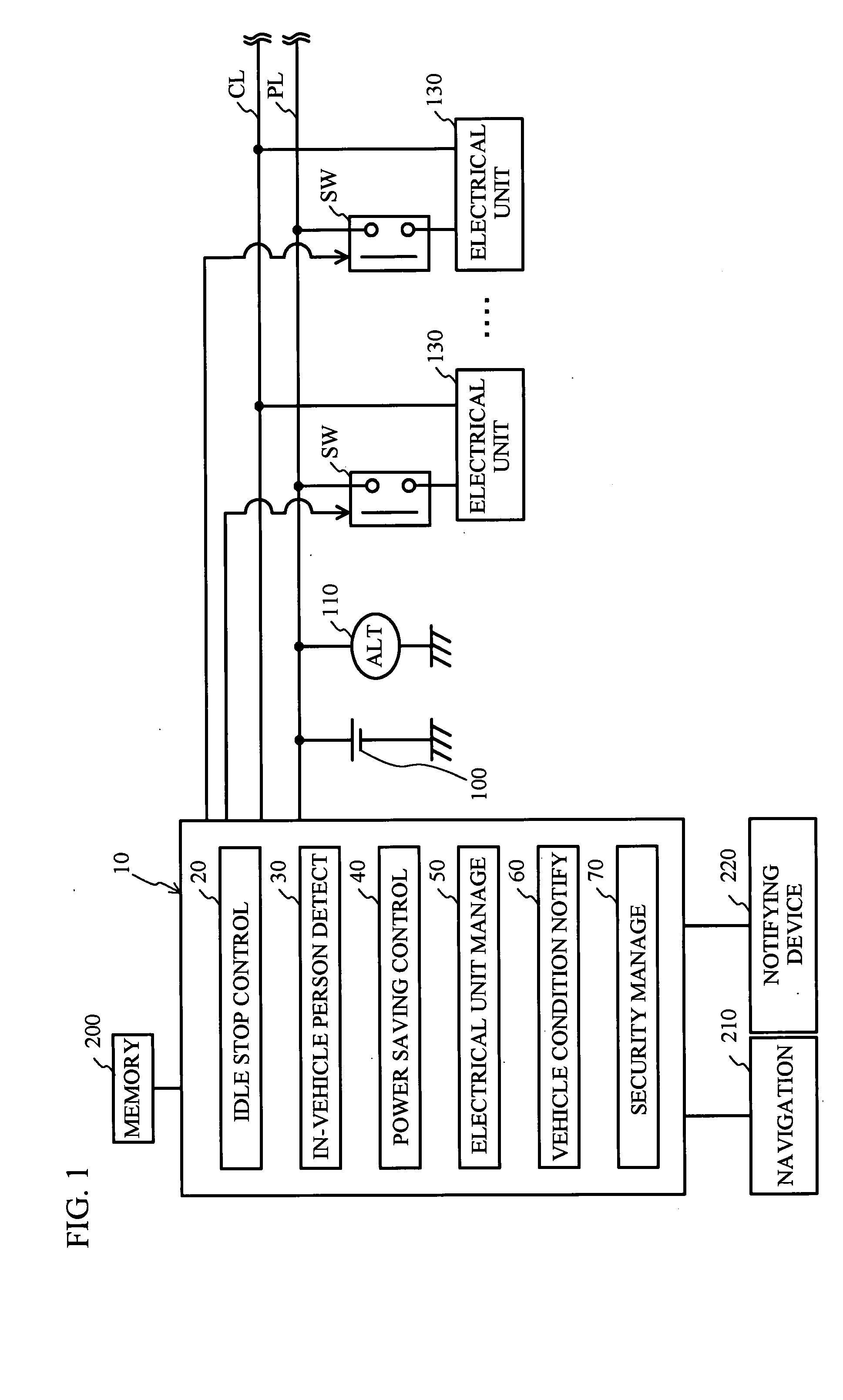
[0021]FIG. 1 is a block diagram of an electrical system of a vehicle to which a system for supervising a vehicle-use battery is applied in accordance with an embodiment of the present invention. Referring to FIG. 1, the electrical system of the vehicle includes an idle stop ECU (Electronic Control Unit) 10 functioning as the vehicle-use battery supervising system, a battery 100, an alternator (ALT) 110 and multiple electrical units 130. Hereinafter, the idle stop ECU 10 is referred to as IS-ECU 10.

[0022]The battery 100 may, for example, be a lead-acid battery and supplies electrical power stored therein to the on-vehicle electrical units. The alternator 110 is driven by an engine on the vehicle through a belt (not shown), and generates an alternating output, which is then rectified by a built-in diode. The resultant DC output is supplied to the electrical units...


PUM


Abstract

A system for supervising a battery mounted on a vehicle, the system includes a first part that detects a person in a vehicle in a stopped state, and a second part that executes a power saving control for reducing power of a battery on the vehicle consumed in electrical units mounted on the vehicle when the first part detects no person in the vehicle.

Description

BACKGROUND OF THE INVENTION[0001]1. Field of the Invention[0002]This invention generally relates to a system and a method for supervising a vehicle-use battery.[0003]2. Description of the Related Art[0004]A vehicle equipped with an idle stop function is known. The idle stop function is aimed at improving fuel economy and reducing the amount of exhaust gas for internal combustion engines on vehicles. When a predetermined condition is met, the engine is stopped. When a predetermined starting condition is met, the engine is automatically restarted. An example of the idle stop function is described in Japanese Patent Application Publication No. 2004-229479.[0005]The following situation may happen to the vehicle equipped with the idle stop function. A user temporarily stops the vehicle in the idle stop state and goes out of the vehicle, so that no person rides on the vehicle. In this case, if the user goes out of the vehicle while an electrical unit such as an air conditioner, a navigati...

Claims


Application Information

Patent Timeline
IPC IPC(8): H02J7/00
CPCB60K28/04H02J7/0032H02J1/14B60R16/03H02J2310/46
Inventor YAMAGUCHI, KAZUHI
Owner FUJITSU GENERAL LTD
Learn More