Micropower voltage-independent capacitance measuring method and circuit

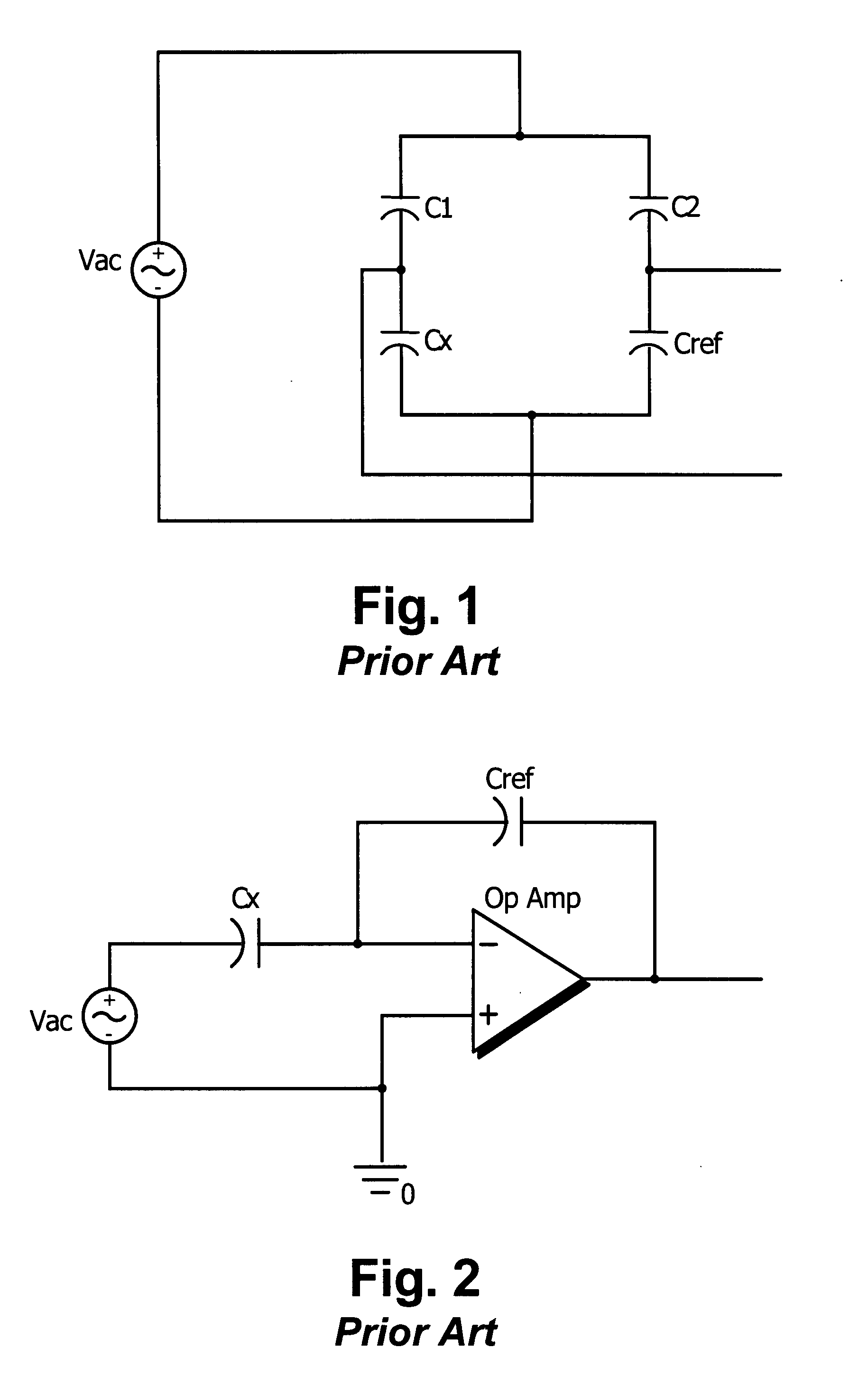
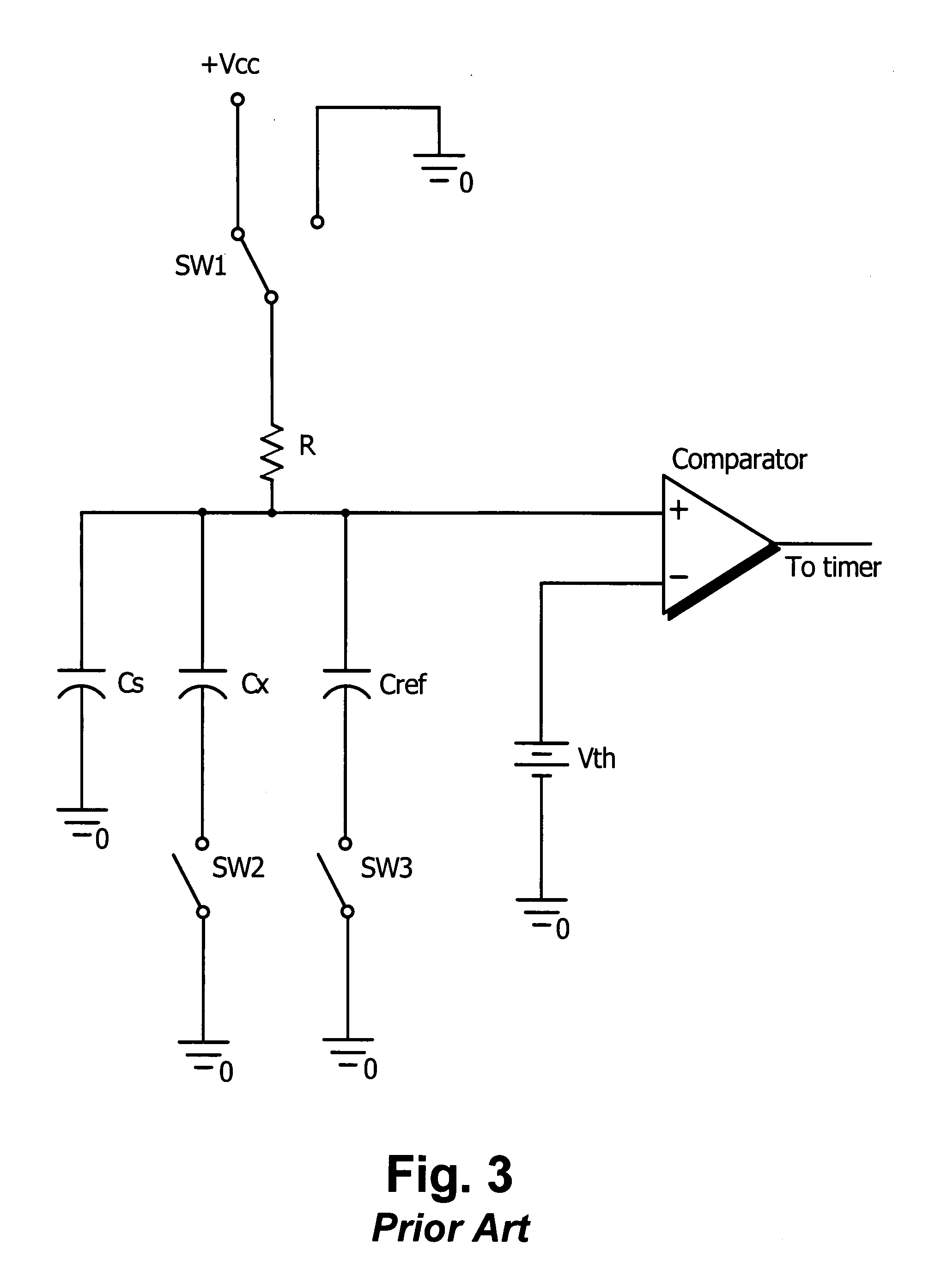
a voltage-dependent capacitance and micro-power technology, applied in the direction of capacitance measurement, resistance/reactance/impedence, instruments, etc., can solve the problems of large affecting the precision of the circuit, the method requires expensive and power-consuming analog front-end circuitry, and the use of relatively high values of cx and cref to achieve accurate measurement of unknown capacitance values

Active Publication Date: 2007-08-23
WEISS INSTR
View PDF17 Cites 21 Cited by
  • Summary
  • Abstract
  • Description
  • Claims
  • Application Information

AI Technical Summary

Benefits of technology

[0009] It is an object of the present invention to provide a capacitance mea

Problems solved by technology

The method requires an expensive and power consuming analog front-end circuitry, and an independent stable AC voltage source for the bridge excitation.
The imperfections of the operational amplifier used in the charge amplifier configuration also heavily affect

Method used


Image

  • Micropower voltage-independent capacitance measuring method and circuit
  • Micropower voltage-independent capacitance measuring method and circuit
  • Micropower voltage-independent capacitance measuring method and circuit

Examples


Embodiment Construction

[0027] The current invention provides a low power voltage independent method and a circuit for high resolution capacitance measurement that overcome all the drawbacks of the prior art examples discussed above.

[0028] The following description and the circuitry are provided for the purpose of illustration and not the limitation of scope of the current invention. It is understood that other types of switches, oscillators and other components can be used without departing from the scope of the invention.

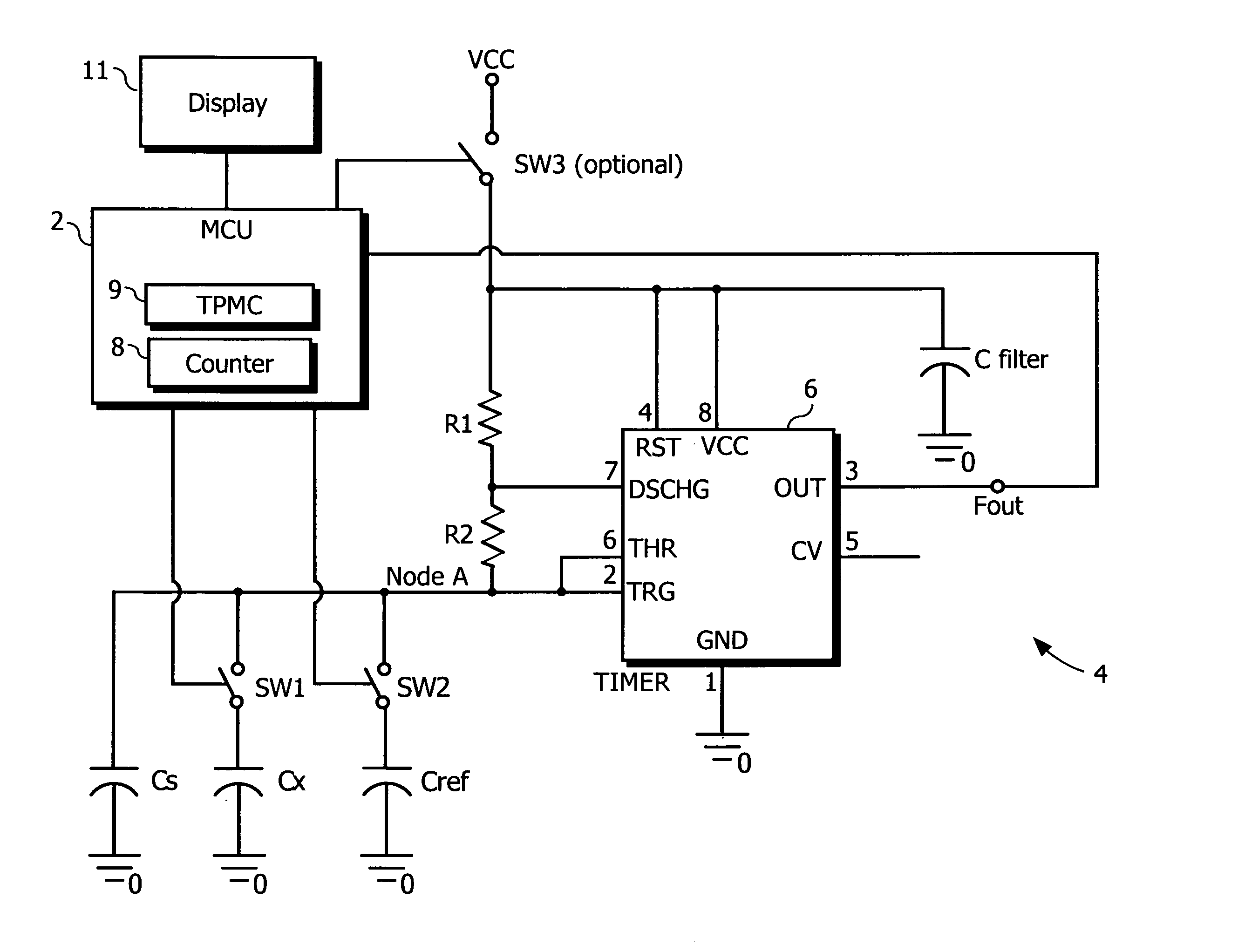
[0029] The preferred embodiment comprises a preferably low-power generic microcontroller 2 and a front end circuit 4. The microcontroller 2 (hereafter MCU) operates the front end circuit 4 and receives a digital signal from the front end circuit 4 in the form of blocks of pulses (periodic signals), each block having its own frequency of pulses or corresponding period. The MCU 2 then processes the signals and outputs the result in any form including but not limited to the display readou...


PUM


Abstract

A circuit for measuring an unknown capacitance includes a reference capacitor having a known capacitance, an oscillator timing circuit, a variable frequency oscillator and a microcontroller. The oscillator timing circuit includes switches which selectively couple the unknown capacitance and the reference capacitor to the oscillator timing circuit. The variable frequency oscillator generates time varying signals which vary in frequency proportionally to the unknown capacitance and reference capacitor selectively coupled to the oscillator timing circuit. The microcontroller receives the time varying signals from the oscillator, and compares the periods of the time varying signals to determine the value of the unknown capacitance. A method of measuring an unknown capacitance includes the steps of generating a first time varying signal which has a period that is proportional to the unknown capacitance, generating a second time varying signal which has a period that is proportional to a known reference capacitance, comparing the periods of the first and second time varying signals and determining the value of the unknown capacitance from the comparison of the periods of the first and second time varying signals.

Description

CROSS-REFERENCE TO RELATED APPLICATION [0001] This application is related to U.S. utility patent application entitled “Light Powered Pressure Gauge”, having Ser. No. 11 / 314,809, filed on Dec. 21, 2005, and having as a named inventor John W. Weiss, U.S. provisional patent application entitled “Capacitance Measuring Circuit”, having Ser. No. 60 / 753,381, filed on Dec. 21, 2005, and having as named inventors Lenny M. Novikov and Lenworth Anderson, and U.S. provisional patent application entitled “Capacitance Measuring Circuit”, having Ser. No. 60 / 753,275, filed on Dec. 22, 2005, and having as named inventors Lenny M. Novikov and Lenworth Anderson, the disclosure of each of which is incorporated herein by reference. Priority is hereby claimed to the aforementioned U.S. provisional patent applications Ser. Nos. 60 / 753,381 and 60 / 753,275.BACKGROUND OF THE INVENTION [0002] 1. Field of the Invention [0003] The present invention generally relates to capacitive sensors, and more particularly r...

Claims


Application Information

Patent Timeline
IPC IPC(8): G01R27/26
CPCG01R27/2605
Inventor NOVIKOV, LENNY M.ANDERSON, LENWORTH
Owner WEISS INSTR
Why Eureka
Try Eureka