
Indicator For A Control Wheel

Inactive Publication Date: 2007-08-23
TENITEK
View PDF9 Cites 17 Cited by
  • Summary
  • Abstract
  • Description
  • Claims
  • Application Information

AI Technical Summary

Benefits of technology

[0015] It is another object of the invention to provide an indicator that is easily retrofittable to controllers, such as steering wheels.
[0016] It is yet another object of the invention to provide an indicator having a minimum number of parts, both to minimize manufacturing costs and to reduce friction.
[0037] Most preferably, the polycarbonate including glass fibers as a filler to minimize shrinkage of the eccentrically weighted annular gear when removing from its mold.

Problems solved by technology

Furthermore, a counter that counts full turns has limited value.
However, there are numerous scenarios where a driver may be confused as to the position of the wheels.
Some drivers find difficulty in judging angles and distances.
If the steering wheel is turned from the centred or “rest” position, there is a possibility of the car lurching forwards or backwards at an angle, and such an occurrence may result in an accident.
One disadvantage of Hwang's solution is that it is necessary to connect the lower rotating disk to the centre of the steering wheel (see Column 3 lines 23 to 25 thereof).
Another disadvantage is that the housing moves relative to the steering wheel, rather than together with the steering wheel.
This relative movement means that the housing cannot be fully sealed and is thus susceptible to the accumulation of dirt and grime on the mechanism, which can prevent the functioning thereof.
Each gear rotates around its axle and there are thus three gears that rotate around axles generating a sizeable amount of friction, which adversely affects reliability of the system.
The weight of the indicator is carried on the main axle and, due to the transmission gears, is not evenly distributed.
In consequence, the axle is susceptible to bending.
Due to the large number of parts, the Hwang's indicator is also expensive to manufacture.
For these among other reasons, the indicator described to Hwang is generally unreliable.
None of the above referenced publications provides a calibrated, unambiguous and reliable indication of the steering wheel angle.
Furthermore, none of the above referenced publications is adaptable to other types of control wheels such as winches or valve wheels.

Method used


Image

  • Indicator For A Control Wheel
  • Indicator For A Control Wheel
  • Indicator For A Control Wheel

Examples


Embodiment Construction

[0047] With specific reference now to the Figures in detail, it is stressed that the particulars shown are by way of example and for purposes of illustrative discussion of preferred embodiments of the present invention only, and are presented in the cause of providing what is believed to be the most useful and readily understood description of the principles and conceptual aspects of the invention. In this regard, no attempt is made to show structural details in more detail than is necessary for a fundamental understanding of the invention.

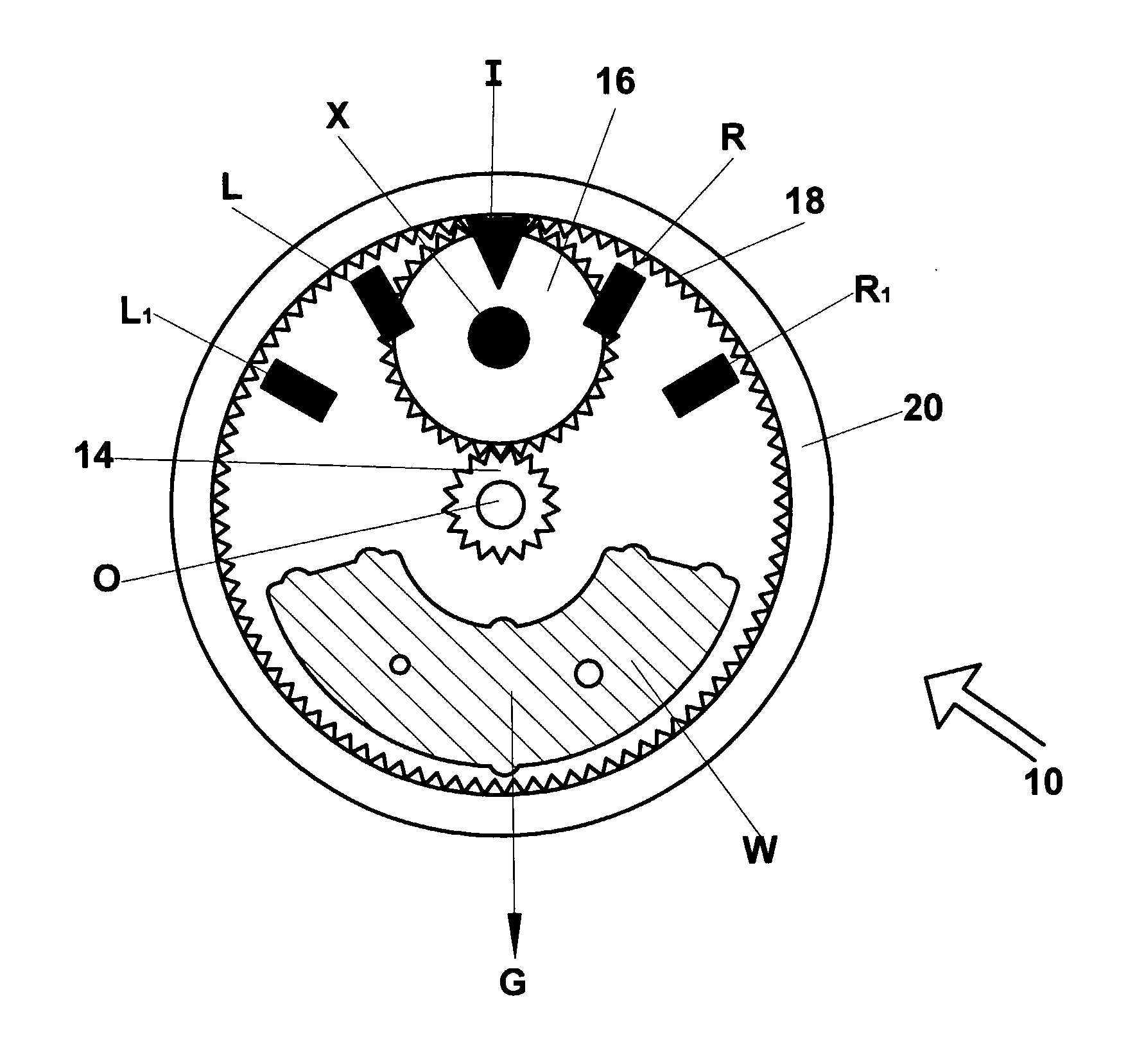
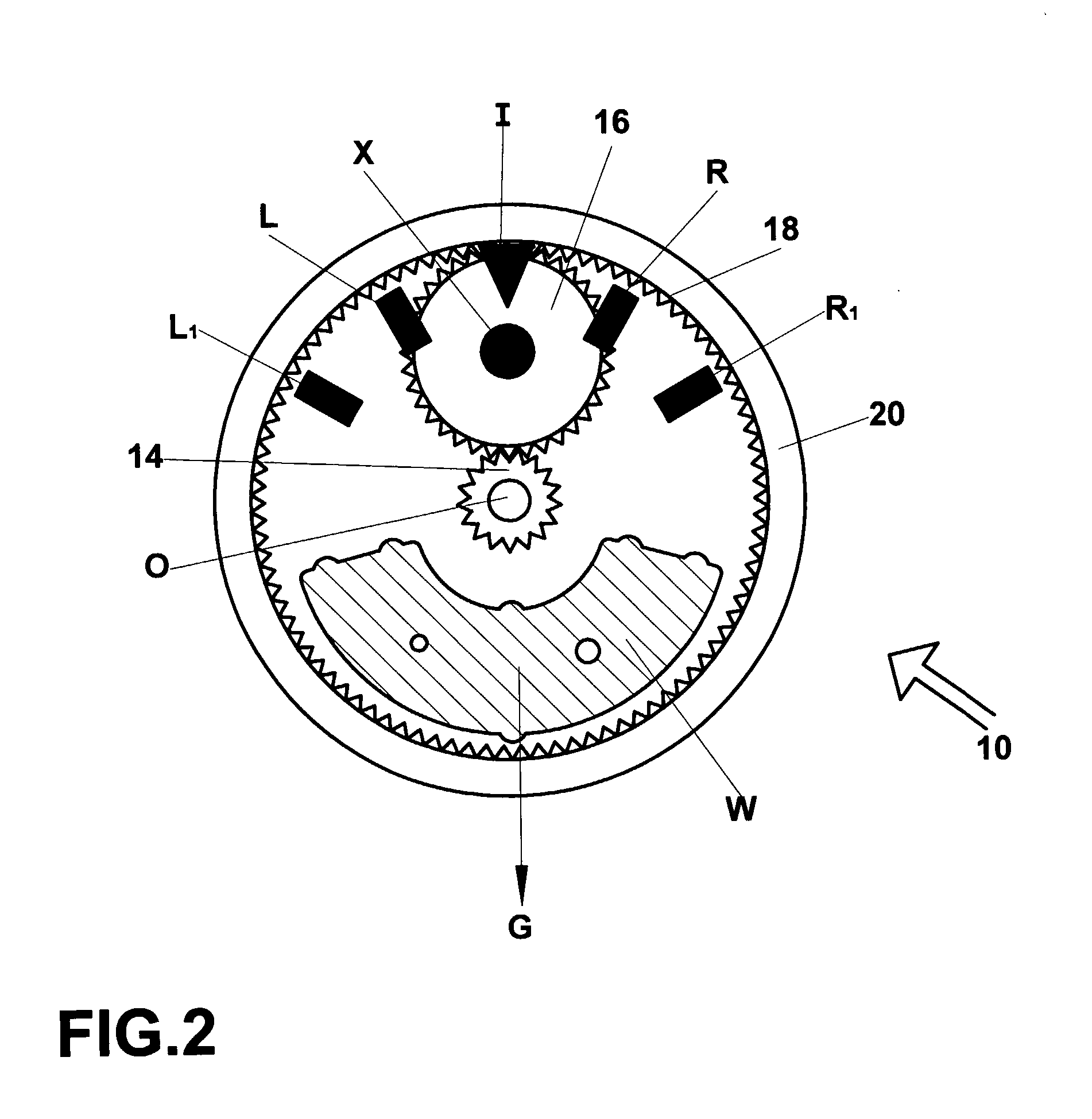
[0048] The description taken with the Figures will make apparent to those skilled in the art how the invention may be embodied in practice. One preferred embodiment is shown in FIGS. 2, 3 and 4; it being noted that similar parts are annotated with similar notations throughout.

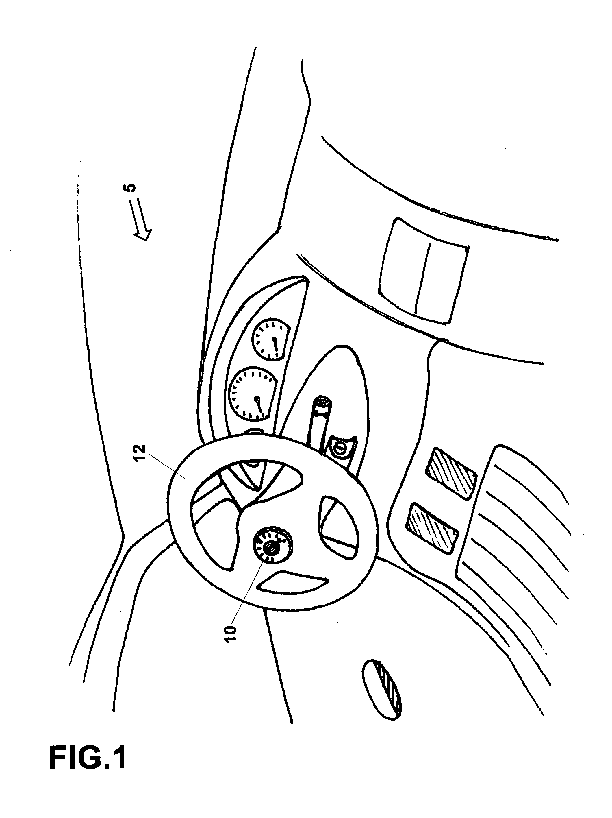
[0049] Referring now to FIG. 1, an indicator 10 coupled to a steering wheel 12 of a vehicle 5 is shown. The indicator 10 indicates the displacement of the steering wheel 12...


PUM


Abstract

An indicator for indicating displacement of a controller displaceable about an axis angled to vertical direction: the indicator comprising an epicyclical gear comprising a sun gear, a planetary gear and an annular gear; the sun gear being coaxial with the annular gear; the annular gear being asymmetrically weighted to be self rightening by gravity; the sun gear being fixable to the controller and serving as a driving gear; the planetary gear being driven around the inside of the annular gear by the sun gear, wherein a centre of the planetary gear serves as a pointer and a reference indication is fixed to the annular gear such that relative position of pointer with respect to reference indication indicates displacement of the controller about its axis.

Description

FIELD OF THE INVENTION [0001] The present invention is directed to providing an indicator for attachment to a control wheel, for giving a visible indication of the rotation of a controller around an axis angled to the vertical, and is further directed to providing a method of use for the indicator. Such an indicator has wide application. One application for such an indicator is to affix to a valve control wheel to indicate the degree to which a valve is opened or closed. Another application of particular interest is to affix the indicator to the steering wheel of a vehicle to indicate the angle through which the wheels of the vehicle are displaced. BACKGROUND OF THE INVENTION [0002] There are a number of levellers that use a plumb bob or the like, to indicate the angle to which a body to which they are attached is displaced from the vertical. Surveying and building apparatus use such a principle. [0003] Electrical knobs such as potentiometers that may be rotated by some angle of up ...

Claims


Application Information

Patent Timeline
IPC IPC(8): B60Q1/00
CPCB62D15/0205G01D13/04G01D5/04
Inventor LIPMAN, AHARON
Owner TENITEK
Learn More