Exposure determining device and exposure determining method

Inactive Publication Date: 2007-08-23
SEIKO EPSON CORP
View PDF2 Cites 11 Cited by
  • Summary
  • Abstract
  • Description
  • Claims
  • Application Information

AI Technical Summary

Benefits of technology

[0013]An advantage of some aspects of the invention is that it provides an exposure determining device and an exposure determining method that are capable of reliably determining whether exposure of an image is appropriate.

Problems solved by technology

When images (photographic images) captured by a digital camera or the like are printed by using a printer or a multifunction machine, printing all the photographed images is very wasteful.
That is, since it is likely that the photographed images include images where exposure is insufficient, it is wasteful to print the images where exposure is insufficient.
In contrast, FIG. 15B illustrates an image where even though a portion of the image is only bright, since the other portions are dark, exposure is insufficient, and the image is not suitable for printing.
As such, generally, for some images, such as an image that is obtained by photographing a firework or night view, exposure may be appropriate, while for other images where a portion thereof is bright but the other portions are dark, exposure may be insufficient.
However, as described above, in the case where with respect to an image for which exposure is to be determined, an average value (hereinafter, also referred to as average luminance value) of luminance values of pixels of the image is calculated and it is determined on the basis of the average value whether exposure of the image is appropriate or insufficient, an erroneous determination may be performed for each image.
Accordingly, it can be understood that if the average luminance values Av are only used, it is difficult to determine that the image shown in FIG. 15A is an image where exposure is appropriate and the image shown in FIG. 15B is an image where exposure is insufficient.

Method used


Image

  • Exposure determining device and exposure determining method
  • Exposure determining device and exposure determining method
  • Exposure determining device and exposure determining method

Examples


first embodiment

Structure of Embodiment

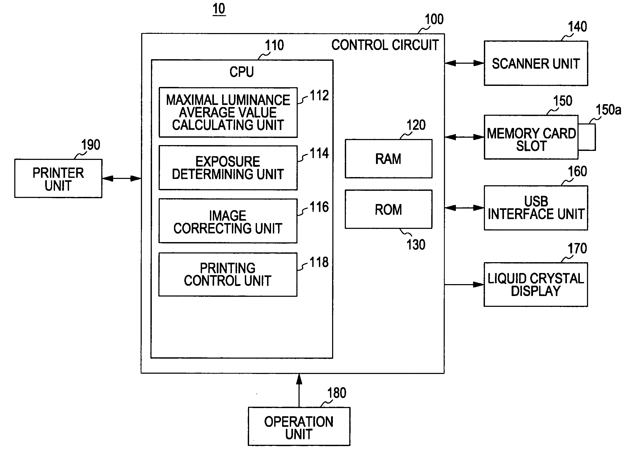
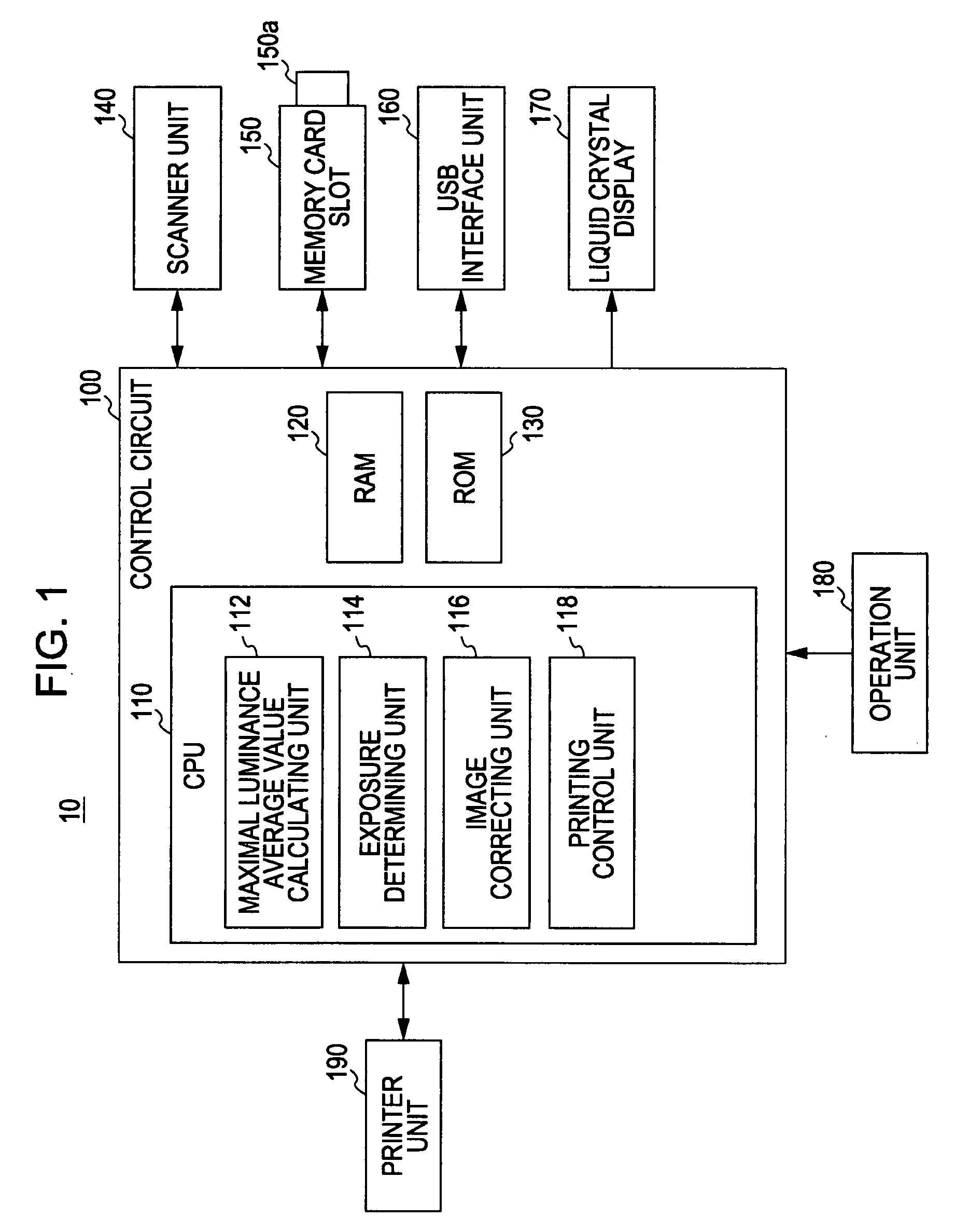
[0059]FIG. 1 is a block diagram illustrating a multifunction machine that includes an exposure determining device according to a first embodiment of the invention. A multifunction machine 10 shown in FIG. 1 includes a control circuit 100 that functions as an exposure determining device and controls various constituent elements to be described below, a scanner unit 140 that reads out an image from a photograph or the like and converts the image into image data, a memory card slot 150 that reads the image data from or writes the image data to the a memory card 150a to be inserted into the memory card slot 150, an USB interface unit 160 that is connected to a digital camera (not shown) or the like through a USB cable (not shown) and reads or writes image data or the like, a liquid crystal display 170 that displays images or various messages, an operation unit 180 that receives various instructions from a user, and a printer unit 190 that prints an image on paper ...

second embodiment

Structure of Embodiment

[0080]FIG. 7 is a block diagram illustrating a multifunction machine that includes an exposure determining device according to a second embodiment of the invention. A multifunction machine 20 shown in FIG. 7 is different from the multifunction machine 10 shown in FIG. 1 in that the CPU 110 executes computer programs and controls as not only the maximum average luminance value calculating unit 112, the exposure determining unit 114, the image correcting unit 116, and the printing control unit 118 but also an average luminance value calculating unit 113. Since the other structure is the same as that of the multifunction machine 10 shown in FIG. 1, the description thereof will be omitted.

[0081]In FIG. 7, the maximum average luminance value calculating unit 112 corresponds to a first evaluation value deriving unit according to the aspect of the invention, the average luminance value calculating unit 113 corresponds to a second evaluation value deriving unit accord...

third embodiment

Structure of Embodiment

[0097]A structure of a multifunction machine that includes an exposure determining device according to a third embodiment of the invention is the same as the structure of the multifunction machine 20 shown in FIG. 7. Therefore, the repetitive description will be omitted.

Operation of Embodiment

[0098]The operation of this embodiment will be described for a case where a user instructs the multifunction machine 20 shown in FIG. 7 to perform ‘entrusted printing’ of all the image data written in the memory card 150a, similar to the cases of the first and second embodiments.

[0099]The operation of the third embodiment is different from the operation of the second embodiment in that an exposure determining process is performed while a threshold value function formula using the average luminance value Av and the maximum average luminance value AvBmax as variables is used as an exposure determining index.

[0100]FIG. 10 is a flowchart illustrating a process flow of an expo...


PUM


Abstract

There is provided an exposure determining device that determines whether exposure of an image represented by image data is appropriate. The exposure determining device includes a first evaluation value deriving unit that derives a maximum luminance reference value for each of blocks obtained by dividing the image into a plurality of blocks of the image data on the basis of luminance values of pixels constituting each block, and derives a first evaluation value for the image on the basis of the derived maximum luminance reference values for the blocks, and an exposure determining unit that determines whether exposure of the image is appropriate, on the basis of the derived first evaluation value.

Description

BACKGROUND[0001]1. Technical Field[0002]The present invention relates to an exposure determining device and an exposure determining method that are capable of determining whether exposure of an image represented by image data is appropriate.[0003]2. Related Art[0004]When images (photographic images) captured by a digital camera or the like are printed by using a printer or a multifunction machine, printing all the photographed images is very wasteful. That is, since it is likely that the photographed images include images where exposure is insufficient, it is wasteful to print the images where exposure is insufficient.[0005]FIGS. 15A and 15B illustrate examples of an image where exposure is appropriate and an image where exposure is insufficient. FIG. 15A illustrates an image obtained by photographing a firework rising toward a night sky, which illustrates an image where even though a background is dark, since bright portions are scattered over the entire image, exposure is appropri...

Claims


Application Information

Patent Timeline
IPC IPC(8): G03F3/08
CPCH04N1/6086H04N1/6027
Inventor MATSUZAKA, KENJI
Owner SEIKO EPSON CORP
Why Eureka
Try Eureka