Substrate conveyor apparatus, substrate conveyance method and exposure apparatus
a conveyor and substrate technology, applied in the direction of conveyors, photomechanical equipment, instruments, etc., can solve the problems of difficult to reliably adhere the reticle to the lower surface of the static chuck, inferior vertical positioning precision, etc., and achieve the effect of high-reliability exposure apparatus
- Summary
- Abstract
- Description
- Claims
- Application Information
AI Technical Summary
Benefits of technology
Problems solved by technology
Method used
Image
Examples
first embodiment
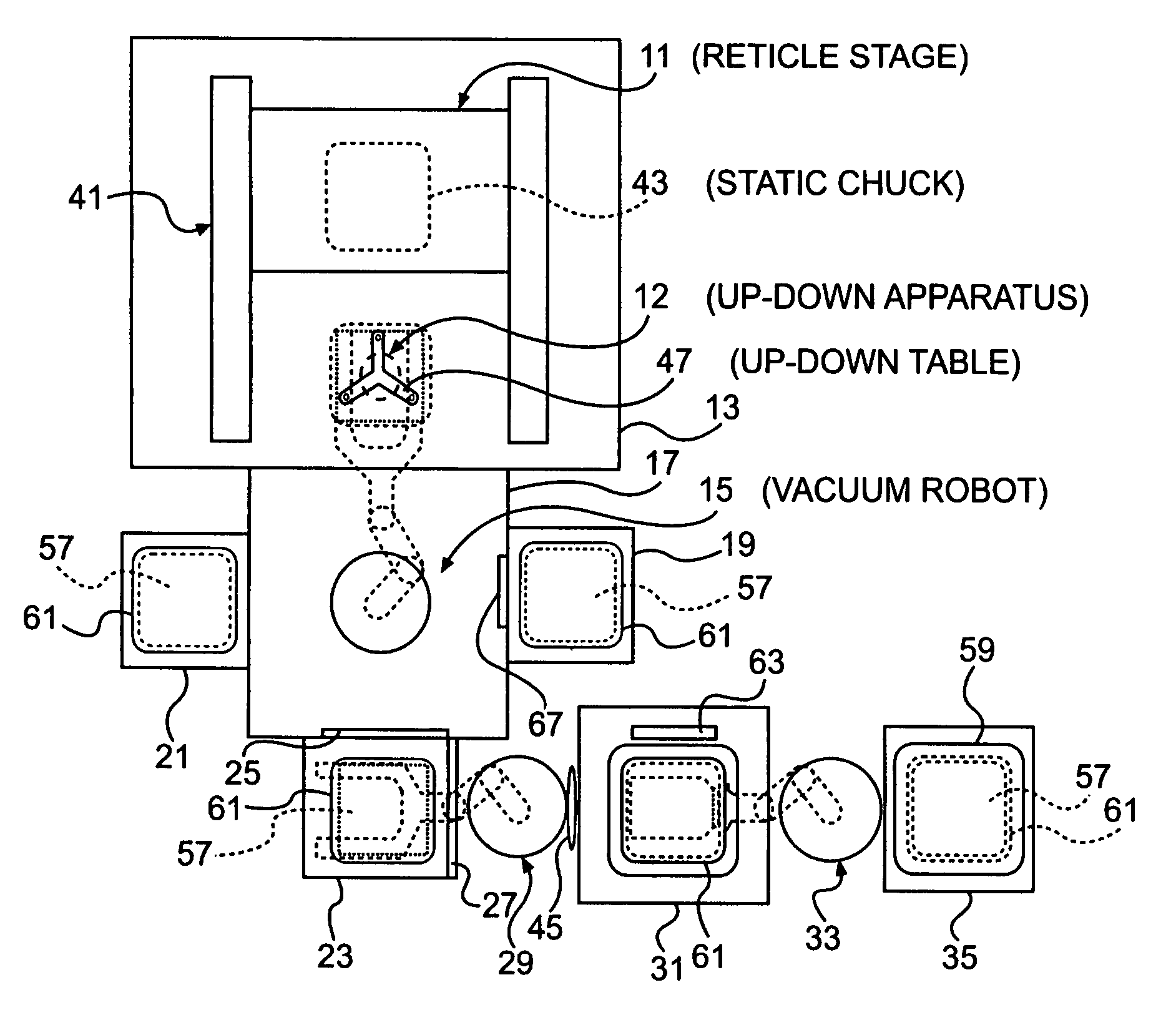
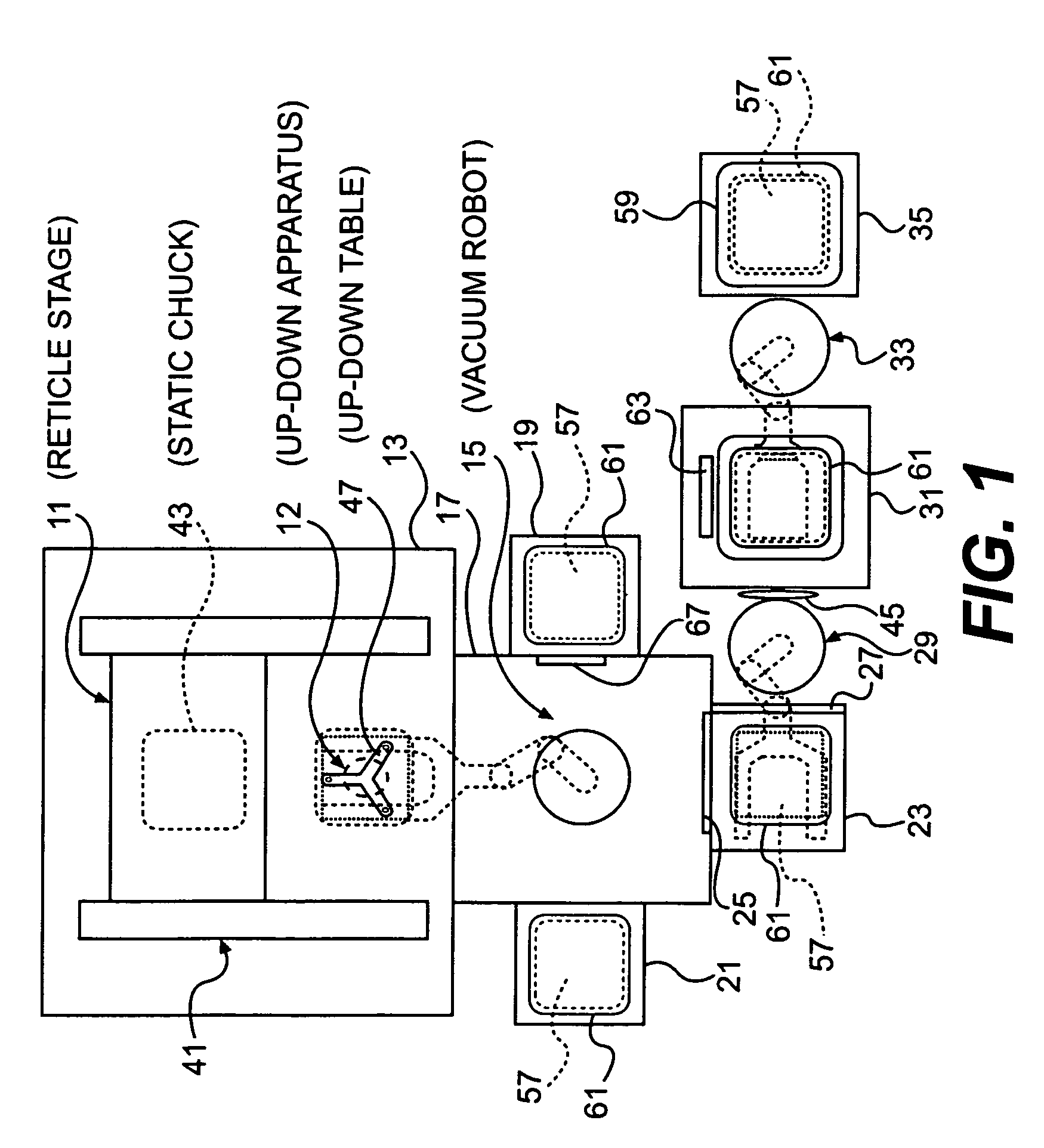
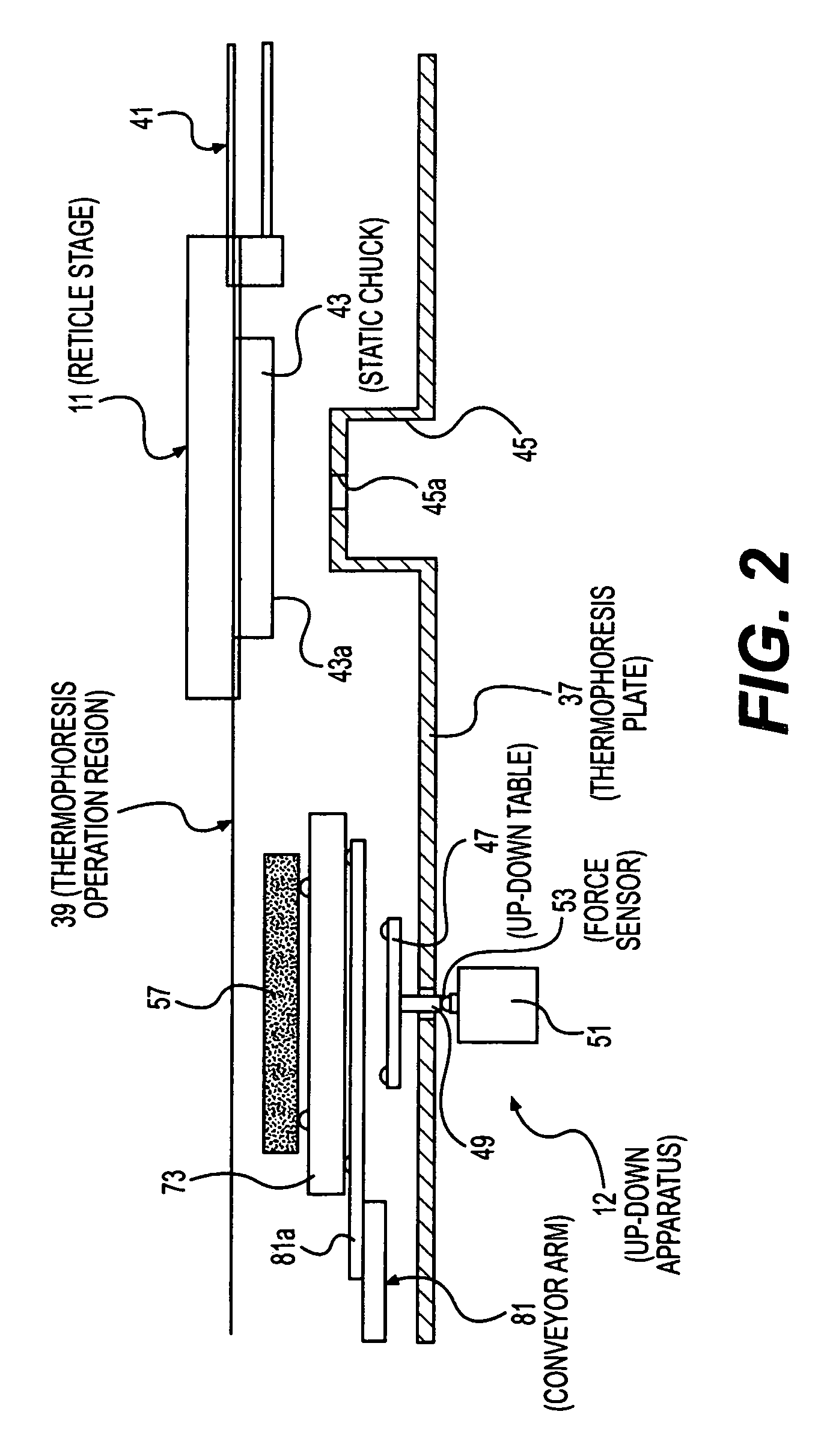
[0041]FIG. 1 shows a first embodiment of the substrate conveyor apparatus of the present invention.
[0042]This substrate conveyor apparatus has an exposure chamber 13 in which are disposed a reticle stage 11 and an up-down apparatus 12. On one side of exposure chamber 13 is provided a robot chamber 17 in which is disposed a vacuum robot 15. On one side of robot chamber 17 is provided a vacuum reticle library 19, and on the other side is provided a clean filter pod opener (hereafter called “CFP opener”) 21. Exposure chamber 13, robot chamber 17, vacuum reticle library 19 and CFP opener 21 are in a vacuum atmosphere.
[0043]In the position on robot chamber 17 opposite exposure chamber 13, a load-lock cell 23 is disposed. Load-lock cell 23 communicates to robot chamber 17 via a second gate valve 25. In addition, it communicates to atmospheric air via a first gate valve 27.
[0044]On the outside of load-lock cell 23, a reticle carrier opener 31 is disposed via a second atmospheric air robot ...
second embodiment
[0070]FIG. 8 shows a second embodiment of the substrate conveyor apparatus of the present invention.
[0071]Note that in this embodiment, the same members as in the first embodiment are assigned the same symbols, so detailed explanation has been omitted.
[0072]In this embodiment, reticle stage 11 has a coarse motion stage 83 and a fine motion table 84.
[0073]Rough motion stage 83 is made movable in the horizontal direction. Below coarse stage 83, a fine motion table 84 is disposed via a Z-actuator 85. Z-actuator 85 moves fine motion table 84 in the up and down direction. Fine motion table 84 is made rotatable in the horizontal direction, vertical direction and on the horizontal plane. A moving mirror 86 is fixed on the side surface of fine motion table 84 in order to measure the position of fine motion table 84. Static chuck 43 is fixed to the lower side of fine motion table 84 with adhesion surface 43a as the lower surface.
[0074]Then, in this embodiment, a drop prevention means is disp...
PUM
 Abstract
Description
Claims
Application Information
 - R&D
- Intellectual Property
- Life Sciences
- Materials
- Tech Scout
- Unparalleled Data Quality
- Higher Quality Content
- 60% Fewer Hallucinations
Browse by: Latest US Patents, China's latest patents, Technical Efficacy Thesaurus, Application Domain, Technology Topic, Popular Technical Reports.
© 2025 PatSnap. All rights reserved.Legal|Privacy policy|Modern Slavery Act Transparency Statement|Sitemap|About US| Contact US: help@patsnap.com


