Substrate conveyor apparatus, substrate conveyance method and exposure apparatus

a conveyor and substrate technology, applied in the direction of photomechanical equipment, instruments, transportation and packaging, etc., can solve the problems of difficult to reliably adhere the reticle to the lower surface of the static chuck, inferior vertical positioning precision, etc., and achieve the effect of high-reliability exposure apparatus

Active Publication Date: 2006-12-28
NIKON CORP
View PDF21 Cites 357 Cited by
  • Summary
  • Abstract
  • Description
  • Claims
  • Application Information

AI Technical Summary

Benefits of technology

[0023] In the exposure apparatus of the present invention, a substrate can be reliably adhered to the lower surface of a chuck; therefore a highly reliable exposure apparatus can be obtained.

Problems solved by technology

However, with the conveyor arm normally used in the substrate conveyor apparatus of Patent Literature 1 and the like, the vertical positioning precision is inferior compared to the horizontal positioning precision; therefore there is the problem that it is difficult to reliably adhere the reticle to the lower surface of the static chuck.

Method used


Image

  • Substrate conveyor apparatus, substrate conveyance method and exposure apparatus
  • Substrate conveyor apparatus, substrate conveyance method and exposure apparatus
  • Substrate conveyor apparatus, substrate conveyance method and exposure apparatus

Examples


first embodiment

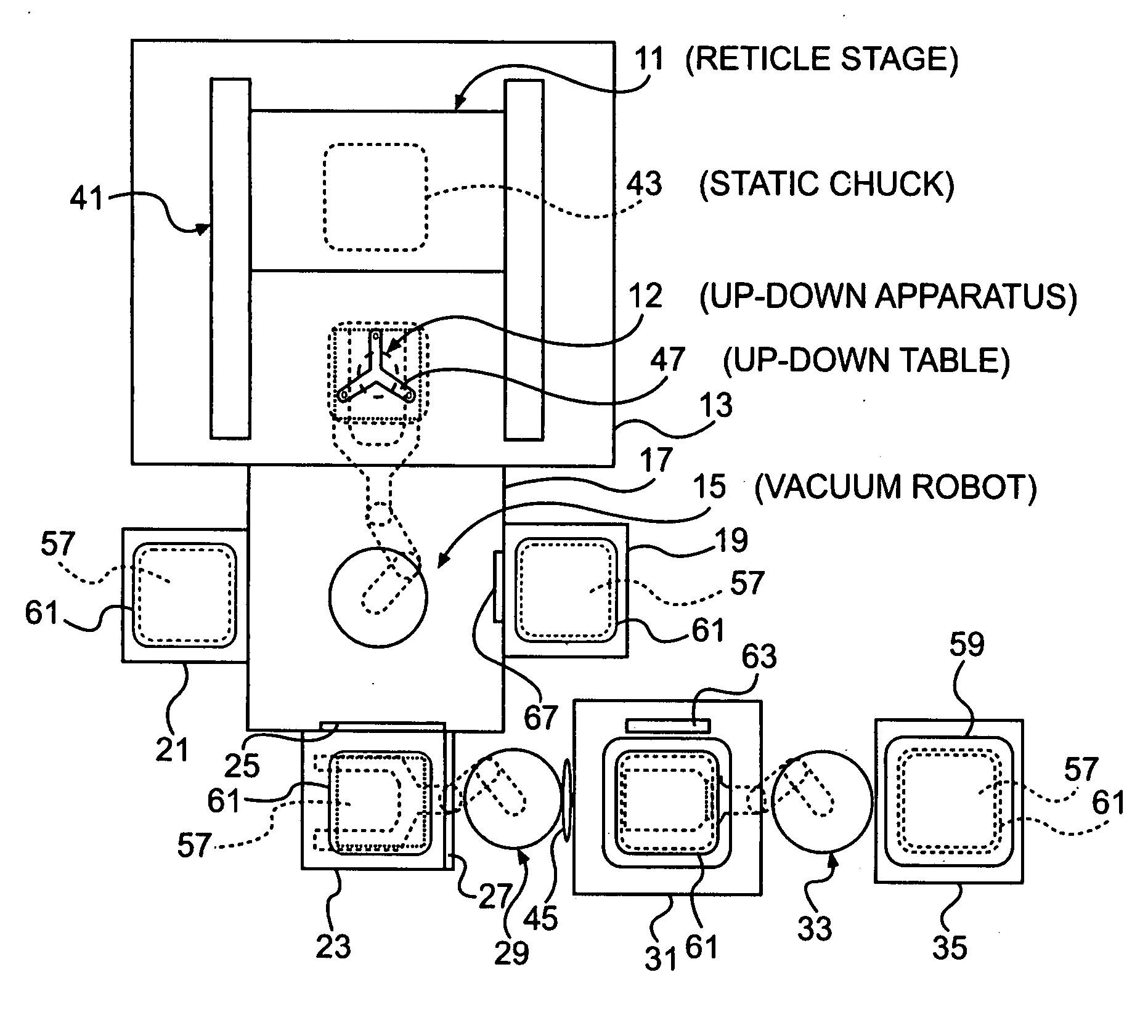
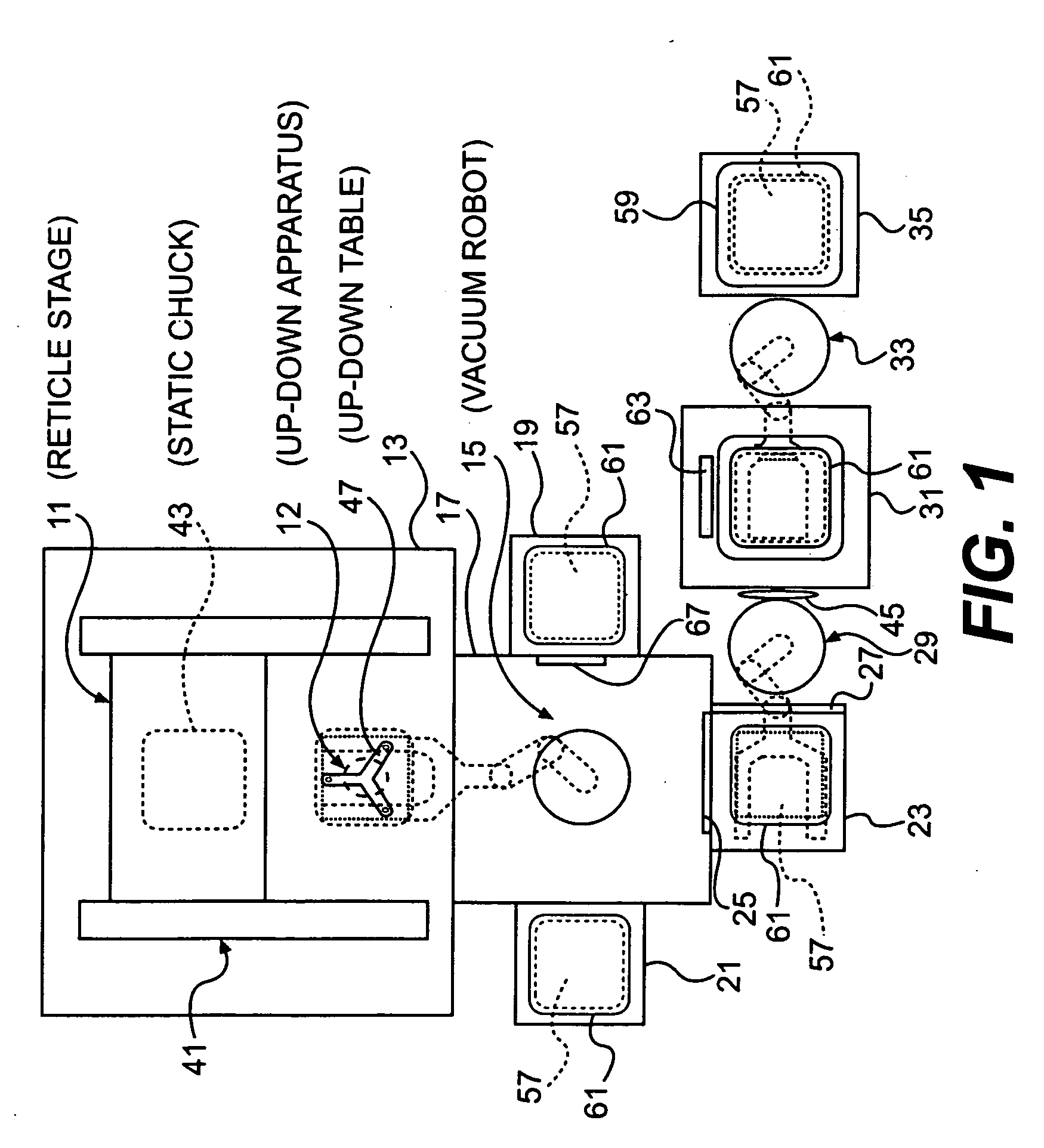
[0041]FIG. 1 shows a first embodiment of the substrate conveyor apparatus of the present invention.

[0042] This substrate conveyor apparatus has an exposure chamber 13 in which are disposed a reticle stage 11 and an up-down apparatus 12. On one side of exposure chamber 13 is provided a robot chamber 17 in which is disposed a vacuum robot 15. On one side of robot chamber 17 is provided a vacuum reticle library 19, and on the other side is provided a clean filter pod opener (hereafter called “CFP opener”) 21. Exposure chamber 13, robot chamber 17, vacuum reticle library 19 and CFP opener 21 are in a vacuum atmosphere.

[0043] In the position on robot chamber 17 opposite exposure chamber 13, a load-lock cell 23 is disposed. Load-lock cell 23 communicates to robot chamber 17 via a second gate valve 25. In addition, it communicates to atmospheric air via a first gate valve 27.

[0044] On the outside of load-lock cell 23, a reticle carrier opener 31 is disposed via a second atmospheric air ...

second embodiment

[0070]FIG. 8 shows a second embodiment of the substrate conveyor apparatus of the present invention.

[0071] Note that in this embodiment, the same members as in the first embodiment are assigned the same symbols, so detailed explanation has been omitted.

[0072] In this embodiment, reticle stage 11 has a coarse motion stage 83 and a fine motion table 84.

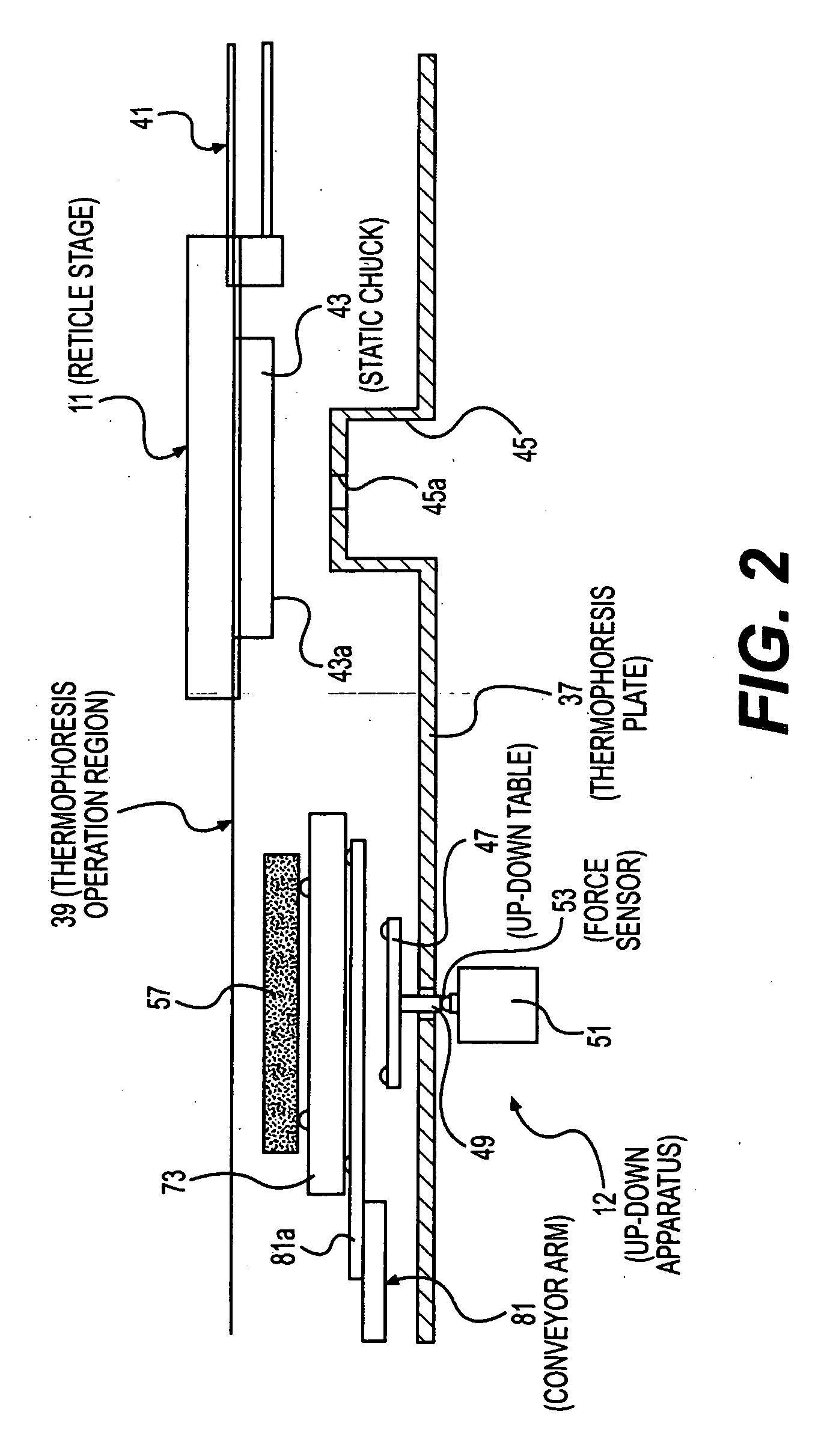
[0073] Rough motion stage 83 is made movable in the horizontal direction. Below coarse stage 83, a fine motion table 84 is disposed via a Z-actuator 85. Z-actuator 85 moves fine motion table 84 in the up and down direction. Fine motion table 84 is made rotatable in the horizontal direction, vertical direction and on the horizontal plane. A moving mirror 86 is fixed on the side surface of fine motion table 84 in order to measure the position of fine motion table 84. Static chuck 43 is fixed to the lower side of fine motion table 84 with adhesion surface 43a as the lower surface.

[0074] Then, in this embodiment, a drop prevention means...


PUM


Abstract

The present invention pertains to a substrate conveyor apparatus that carries a substrate such as a reticle, a substrate conveyance method and an exposure apparatus, with the object of reliably adhering a substrate to the lower surface of a chuck. The present invention is characterized by having a movable stage that can move in the horizontal direction and that is equipped with a chuck having an adhesion surface that faces down for adhering a substrate, an up-down means equipped with an up-down table that is positionable in a position below the substrate and within the movement range of the movable stage, and a conveyance means equipped with a conveyor arm that carries the substrate to the up-down means.

Description

CROSS REFERENCE TO RELATED APPLICATIONS [0001] This application claims the priority of Japanese Patent Application No. 2004-330356, filed on Nov. 15, 2004, and the benefit of U.S. Provisional Application No. 60 / 721,128, filed on Sep. 28, 2005, the contents of which are incorporated herein by reference.BACKGROUND OF THE INVENTION [0002] 1. Field of the Invention [0003] The present invention pertains to a substrate conveyor apparatus that carries substrates such as reticles, to a substrate conveyance method and to a substrate conveyor apparatus. [0004] 2. Brief Description of the Prior Art [0005] In prior art, as shown in Patent Literature 1, for example, a substrate conveyor apparatus that carries a reticle below a reticle stage by means of a conveyor arm and holds the reticle to the lower surface of a static chuck that is fixed to the lower side of the reticle stage is known. [0006] Patent Literature 1: Unexamined Japanese Patent Application Publication H11-74182 Official gazette. [...

Claims


Application Information

Patent Timeline
Patent Type & Authority Applications(United States)
IPC IPC(8): B65H1/00
CPCG03F7/70741
Inventor TANAKA, KEIICHI
Owner NIKON CORP
Why Eureka
Try Eureka