
Method To Minimize Excess Cable Length

a technology of excess cable length and method, applied in the direction of fibre mechanical structure, instruments, optics, etc., can solve the problem of storage of excess fiber cables, and achieve the effect of eliminating fiber excess length and eliminating the cost of logistics and handling of different pre-connectorized cables

Inactive Publication Date: 2007-08-23
TELEFON AB LM ERICSSON (PUBL)
View PDF23 Cites 0 Cited by
  • Summary
  • Abstract
  • Description
  • Claims
  • Application Information

AI Technical Summary

Benefits of technology

[0011] A purpose with the invention is to eliminate fiber excess length when connecting equipment in separate equipment cabinets.
[0012] Yet another advantage is that the cost of logistics and handling of different pre-connectorized cables are eliminated.

Problems solved by technology

A challenge for large-scale point-to-point Fiber-To-The-Home installations is the large amount of fibers to terminate and route to active equipment in a central office.
Storage of excess fiber cables is a problem that is well known, see for example U.S. Pat. No. 5,708,751.

Method used


Image

  • Method To Minimize Excess Cable Length
  • Method To Minimize Excess Cable Length
  • Method To Minimize Excess Cable Length

Examples


Embodiment Construction

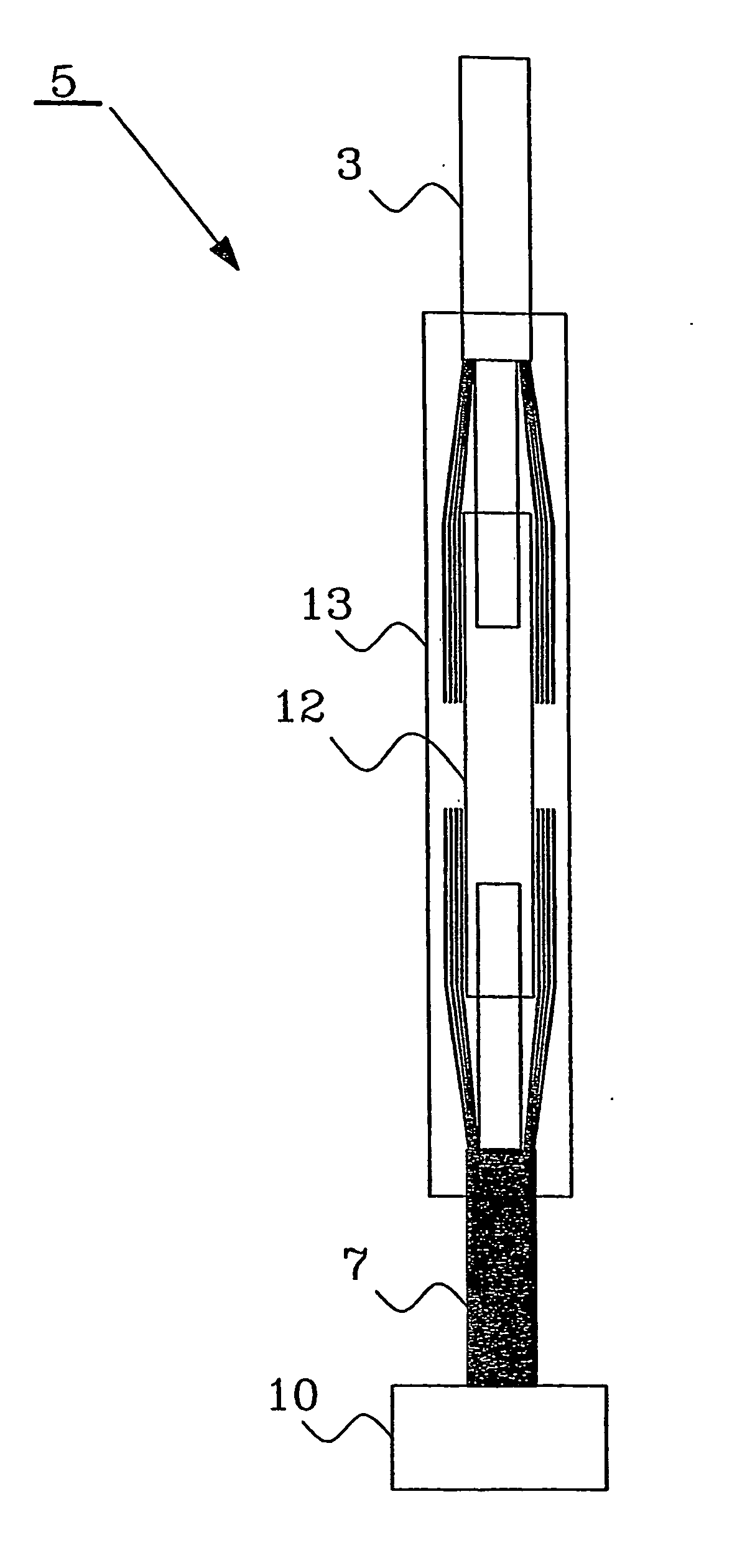
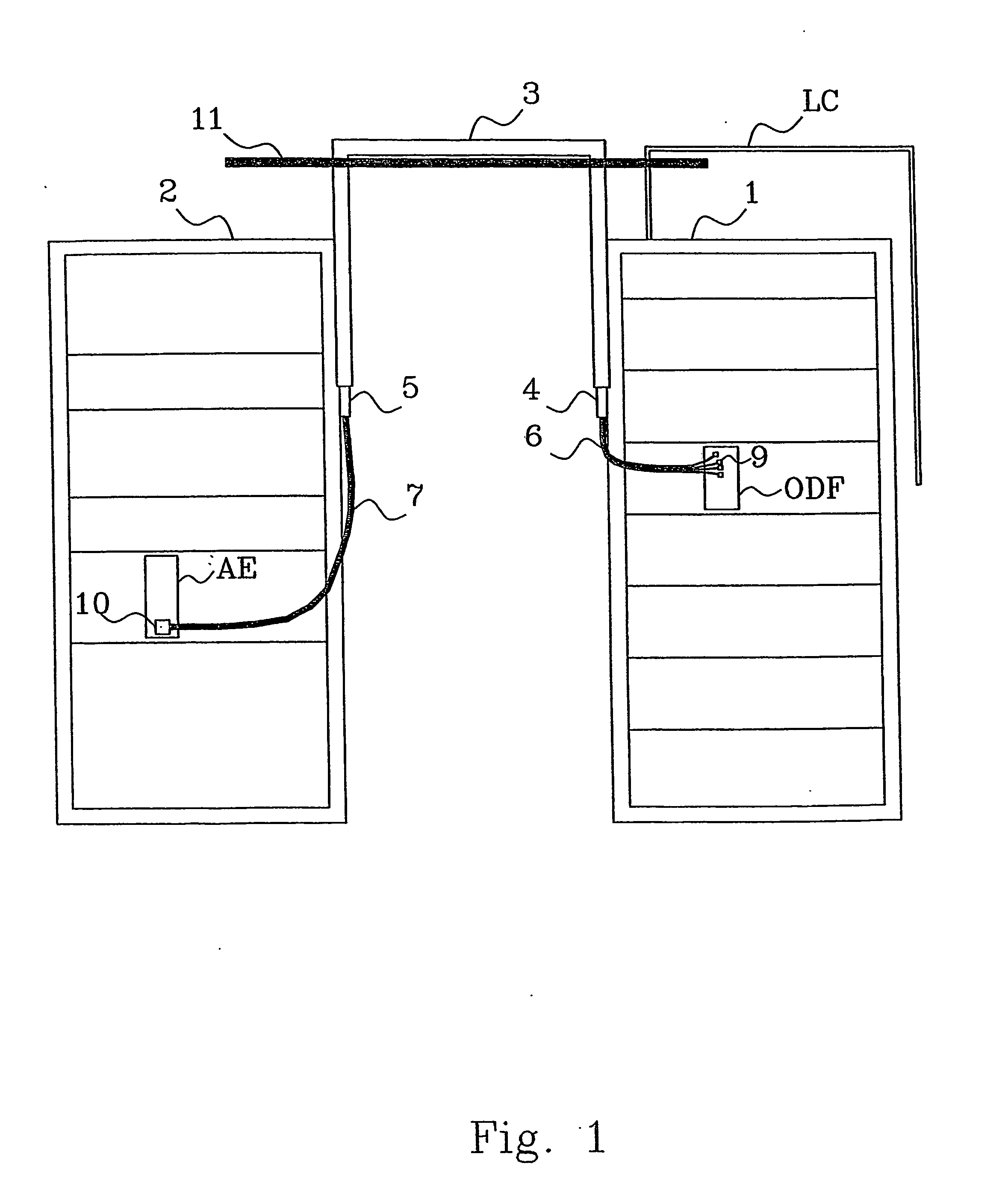
[0017]FIG. 1 discloses two equipment cabinets, a first cabinet 1 and a second cabinet 2. The first cabinet 1 is in this example an optical distribution frame ODF cabinet and comprises passive equipment like ODFs having individual MU connectors 9. The second cabinet 2 is an active equipment cabinet with eight channel array transmitters. Two fibers per subscriber is used, one for up link and one for down link. The ODF is used as an interface between the optical fiber cable system represented by a line cable LC in FIG. 1, and active equipment AE in the second cabinet 2.

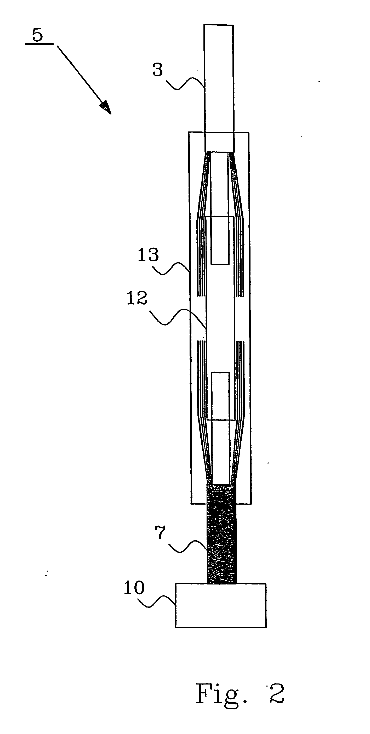
[0018] For a system similar to the one disclosed in the schematic FIG. 1, 480 ribbon cables with 8 fibers each are necessary to connect the active equipment cabinet with the ODF cabinet. On the ODF side an 8-f ribbon fan-out cable 6 to single MU fan-out casing 4 is used. The fan-out casing 4 can be handled as part of the cable and hangs inside the cabinet, sufficiently close to an ODF panel for the MU connectors to reac...


PUM


Abstract

The present invention relates to method and arrangement to minimize excess fiber cable in large-scale point-to-point fiber installations, between equipment ODF, AE located in different equipment cabinets 1, 2. Each cabinet comprises at least one casing 4, 5, which casings are arranged to connect fiber cables with equipment in the cabinets via fan-out fiber cables 6, 7. The method comprises the following steps: Attaching one end of a ribbon fiber cable 3 to a casing 4 that is adherent to a first equipment cabinet 1. Routing of the ribbon fiber cable with a minimum excess length to a casing 5 adherent to a second equipment cabinet 2. Cutting the other end of the ribbon fiber cable 3. Attaching the cut end of the ribbon fiber cable 3 to the casing 5 adherent to the second equipment cabinet 2.

Description

TECHNICAL FIELD OF THE INVENTION [0001] The present invention relates to methods and arrangements to minimize excess length of fiber cable between different equipment locations. DESCRIPTION OF RELATED ART [0002] A challenge for large-scale point-to-point Fiber-To-The-Home installations is the large amount of fibers to terminate and route to active equipment in a central office. In a future scenario with all-fiber access, i.e. fiber replaces the current copper access, thousands of fibers or more could be terminated at one side. At these large sites, the optical distribution could be placed at one floor, while the active equipment could be placed at a different floor. This further emphasizes the importance of a flexible and cost effective fiber management solution in the central office. In a typical installation of today the outside plant fiber cable entering the central office must be terminated in a joint closure where it is fusion spliced to an indoor cable that terminates in a net...

Claims


Application Information

Patent Timeline
Patent Type & Authority Applications(United States)
IPC IPC(8): G02B6/44G02BG02B6/46
CPCG02B6/46
Inventor MICKELSSON, HANSCAGENIUS, TORBJORN
Owner TELEFON AB LM ERICSSON (PUBL)
Learn More