Partial DPSK (PDPSK) Transmission Systems

a transmission system and partial dpsk technology, applied in electromagnetic transmission, electrical equipment, transmission, etc., can solve the problems of poor filter tolerance relatively poor osnr receiver sensitivity of psbt, and low ber of dpsk transmission systems

Active Publication Date: 2007-08-23
LUMENTUM OPTICS INC
View PDF12 Cites 58 Cited by
  • Summary
  • Abstract
  • Description
  • Claims
  • Application Information

AI Technical Summary

Problems solved by technology

Also, existing systems sometimes include many cascaded optical add-drop multiplexers.
However, PSBT has relatively poor OSNR receiver sensitivity, meaning that it requires a relatively high OSNR to obtain a low BER.
However, DPSK transmission systems do not have good filter tolerance.
However, DQPSK transmission systems have approximately 1.5-2 dB worse receiver sensitivity than DPSK transmission systems.
Furthermore, both the transmitter and the receiver are significantly more complex than DPSK transmitter / receiver.
It is also conventional wisdom that using delay interferometers with a delay that is shorter or longer than the symbol time slot will result in some receiver performance penalties when receiving DPSK and DQPSK signals.

Method used


Image

  • Partial DPSK (PDPSK) Transmission Systems
  • Partial DPSK (PDPSK) Transmission Systems
  • Partial DPSK (PDPSK) Transmission Systems

Examples


Embodiment Construction

[0023] While the present teachings are described in conjunction with various embodiments and examples, it is not intended that the present teachings be limited to such embodiments. On the contrary, the present teachings encompass various alternatives, modifications and equivalents, as will be appreciated by those of skill in the art.

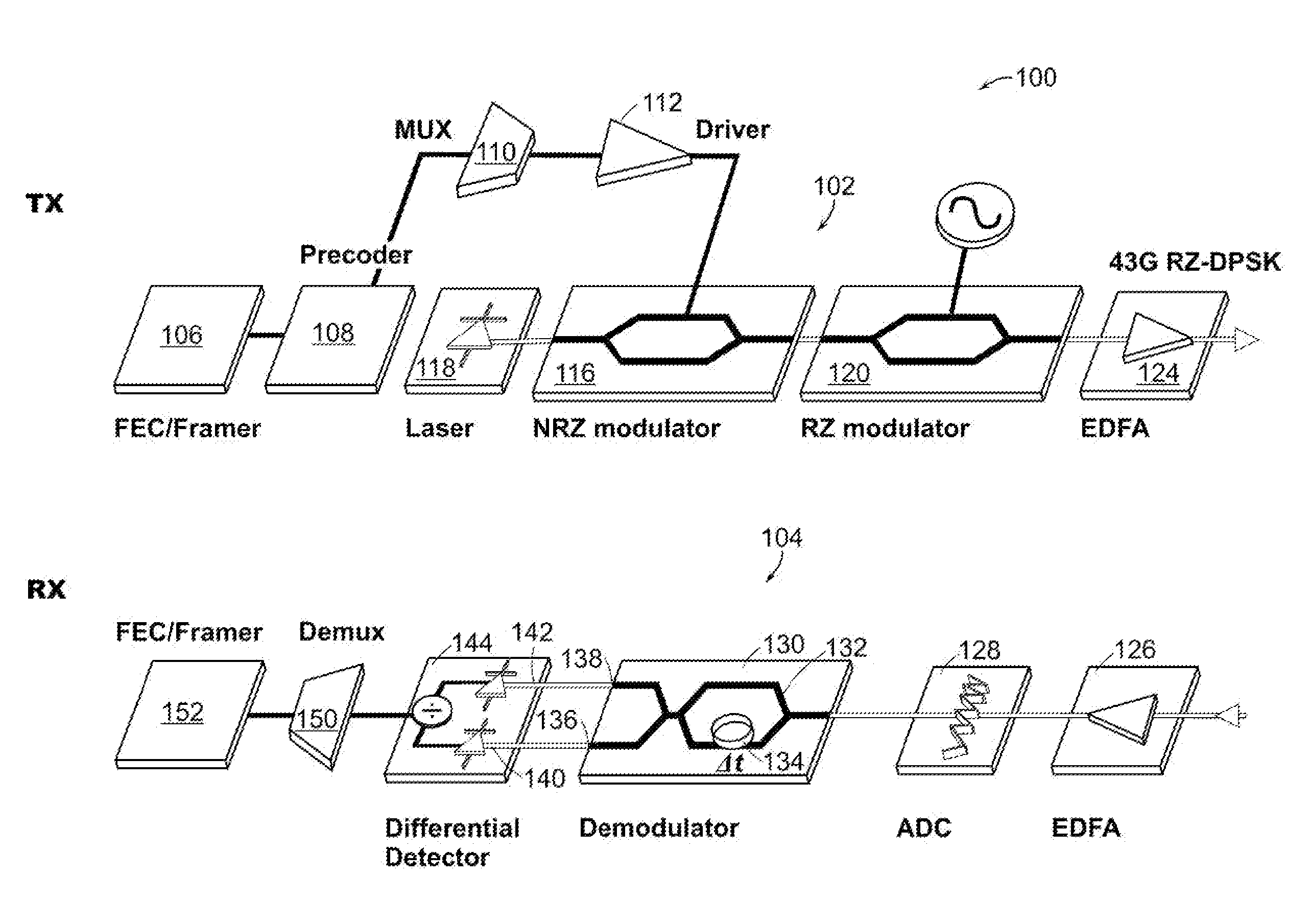
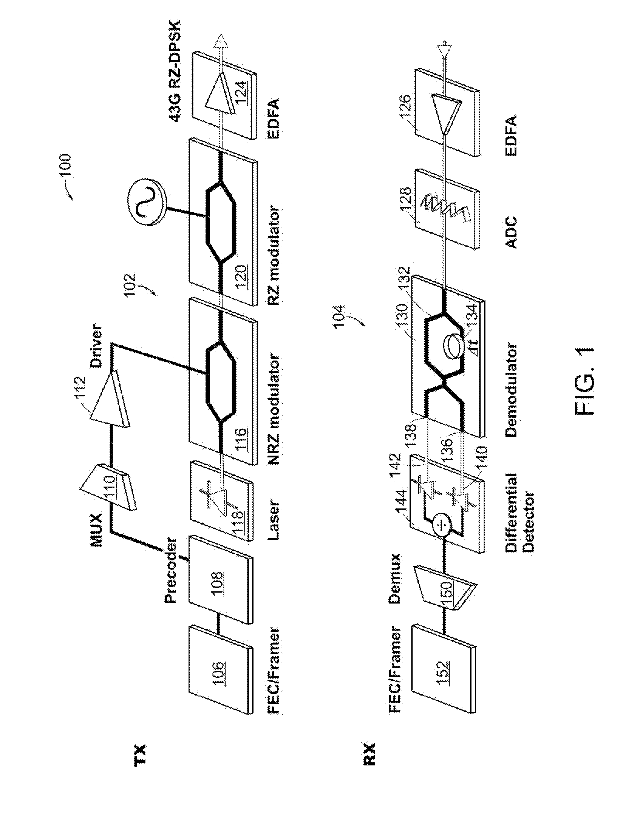
[0024] For example, it should be understood that there are numerous variations of the PDPSK receivers according to the present invention. In particular, it should be understood that the methods and apparatus of the present invention are not limited to any particular type of demodulator. In addition, it should be understood that the methods and apparatus of the present invention can be used with any type of multilevel phase modulation including RZ and NRZ types of modulation.

[0025] It should be understood that the individual steps of the methods of the present invention may be performed in any order and / or simultaneously as long as the invention remains...


PUM


Abstract

An optical receiver includes a demodulator having a delay interferometer comprising an optical input that receives a phase modulated optical signal from a bandwidth limited transmission system. The delay interferometer has a free spectral range that is larger than a symbol rate of the phase modulated optical signal by an amount that improves receiver performance. The receiver also includes a differential detector having a first and a second photodetector. The first photodetector is optically coupled to the constructive optical output of the delay interferometer. The second photodetector is optically coupled to the destructive optical output of the delay interferometer. The differential detector combines a first electrical detection signal generated by the first photodetector and a second electrical detection signal generated by the second photodetector to generate an electrical reception signal.

Description

RELATED APPLICATION SECTION [0001] This application claims priority to U.S. Provisional Patent Application Ser. No. 60 / 795,121, filed Apr. 26, 2006, entitled “Quasi Differentially Demodulated DPSK and Quasi Differentially Demodulated DQPSK Modulation Formats (QD-PSK / QD-QPSK)”, the entire application of which is incorporated herein by reference.BACKGROUND SECTION [0002] DWDM optical fiber transmission systems operating at channel rates of 40 Gb / s and higher are highly desirable because they potentially have greater fiber capacity and also have lower cost per transmitted bit compared to lower channel rate systems. Currently, many DWDM optical fiber transmission systems operate at a channel rate of 10 Gb / s. It is desirable for these 40 Gb / s transmission systems to be compatible with the currently existing 10 Gb / s transport architectures. [0003] The modulation format of 40 Gb / s DWDM transmission systems must be chosen to have high Optical Signal-to-Noise Ratio (OSNR) sensitivity. High O...

Claims


Application Information

Patent Timeline
Patent Type & Authority Applications(United States)
IPC IPC(8): H04B10/00
CPCH04B10/505H04B10/5051H04B10/66H04B10/5162H04B10/5561H04B10/5055
Inventor MIKKELSEN, BENNYMAMYSHEV, PAVELRASMUSSEN, CHRISTIANLIU, FENGHAI
Owner LUMENTUM OPTICS INC
Why Eureka
Try Eureka