Motor-compressor

a motor and compression tube technology, applied in the field of motor compression tubes, can solve the problems of increasing the number of components and affecting the operation and requiring significant maintenance, so as to increase the number of components and the complexity of the motor compression tub

Active Publication Date: 2007-08-23
NUOVO PIGNONE TECH SRL
View PDF19 Cites 44 Cited by
  • Summary
  • Abstract
  • Description
  • Claims
  • Application Information

AI Technical Summary

Benefits of technology

[0007] This however consequently increases the number of components and complexity of the motor-compressor.

Problems solved by technology

In certain cases, these bearings are lubricated with oil: this has the disadvantage of the use of control and management systems of the lubricating oil with consequent high encumbrances and significant maintenance interventions.
This however consequently increases the number of components and complexity of the motor-compressor.

Method used


Image

  • Motor-compressor
  • Motor-compressor

Examples


Embodiment Construction

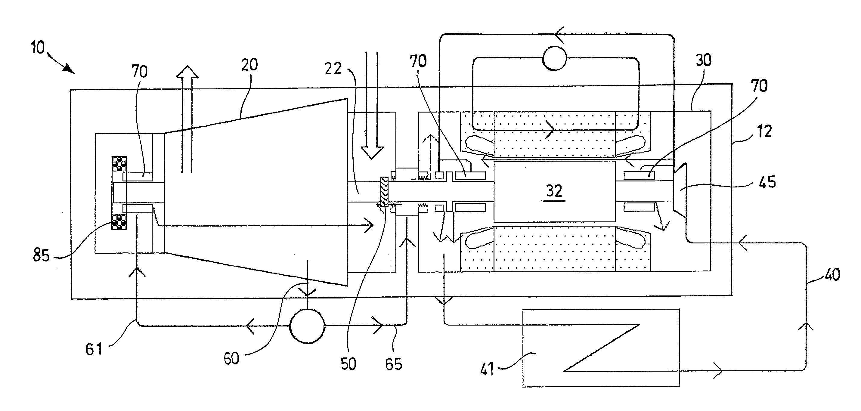
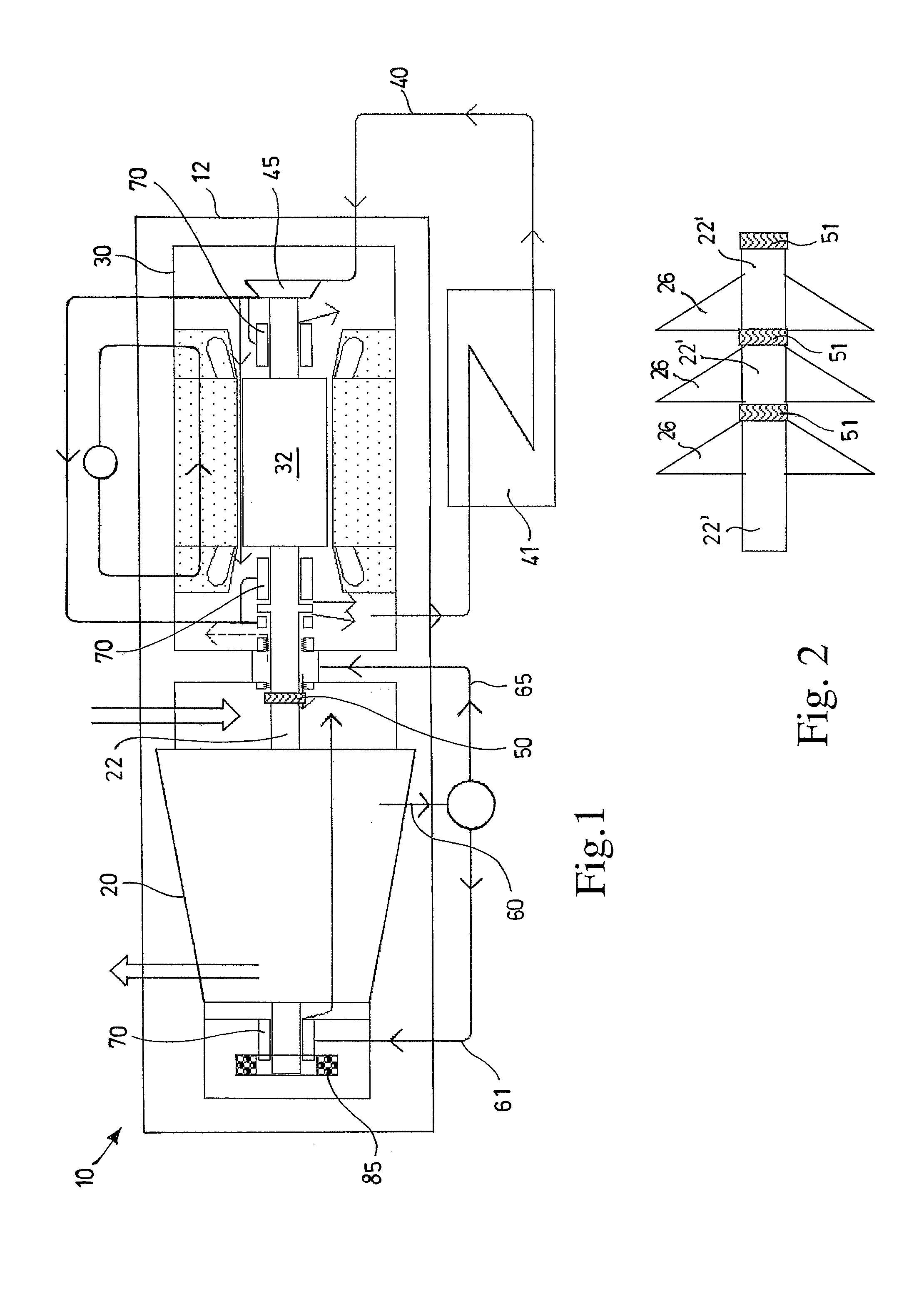
[0017] With reference to the figures, these show a motor-compressor 10 comprising a compressor 20 and an electric motor 30 directly connected to said compressor 20, which are integrated in a single unit.

[0018] In particular, said motor-compressor 10 comprises a single box or casing 12 in which said compressor 20 and said electric motor 30 are housed.

[0019] Said compressor 20 and said electric motor 30 are preferably not separated and the same type of gas (process gas processed by the compressor) pass through both.

[0020] Although process gas contains potentially corrosive / erosive agents, capable of degrading the electric parts in an extremely rapid time, (in particular the motor 30 coils and magnetic bearings 70 of the rotor), the motor-compressor 10 according to the present invention comprises a protection system of the motor windings and magnetic bearings from the process gas based on the use of barriers.

[0021] Said motor-compressor 10 preferably comprises three active radial m...


PUM


Abstract

Motor-compressor comprising a compressor, an electric motor directly connected to said compressor, wherein the compressor and the electric motor are integrated in a single unit, housed in a single box or casing.

Description

FIELD OF THE INVENTION [0001] The present invention relates to a motor-compressor used for the compression of process gas, in particular used for applications in which a reduced maintenance and high reliability are required, and more specifically used in applications in underwater environments. BACKGROUND OF THE INVENTION [0002] A motor-compressor normally comprises a compressor of process gas and an electric motor for activating said compressor. [0003] These are typically coupled with each other by means of a joint, which connects a portion of a shaft of the compressor, extending from its box or casing, to a corresponding portion of a rotor of an electric motor, which in turn extends from the box or casing of the same electric motor. [0004] Both the motor and the compressor are equipped with at least a pair of radial bearings for supporting the corresponding rotor. [0005] In certain cases, these bearings are lubricated with oil: this has the disadvantage of the use of control and m...

Claims


Application Information

Patent Timeline
Patent Type & Authority Applications(United States)
IPC IPC(8): F04F1/06
CPCF04D29/05F04D29/054F04D29/058F04D25/0686F04D29/624F16C37/005F16C32/047F04D29/601F16C2326/00F16C2360/44F16C2326/30
Inventor FROSINI, FRANCOCAMATTI, MASSIMOROSSI, EUGENIOVANNINI, GUISEPPETASSELLI, SABRINA
Owner NUOVO PIGNONE TECH SRL
Why Eureka
Try Eureka