Magnetic flow cytometer with SQUID microscopy

Inactive Publication Date: 2007-08-23
VANDERBILT UNIV
View PDF0 Cites 31 Cited by
  • Summary
  • Abstract
  • Description
  • Claims
  • Application Information

AI Technical Summary

Benefits of technology

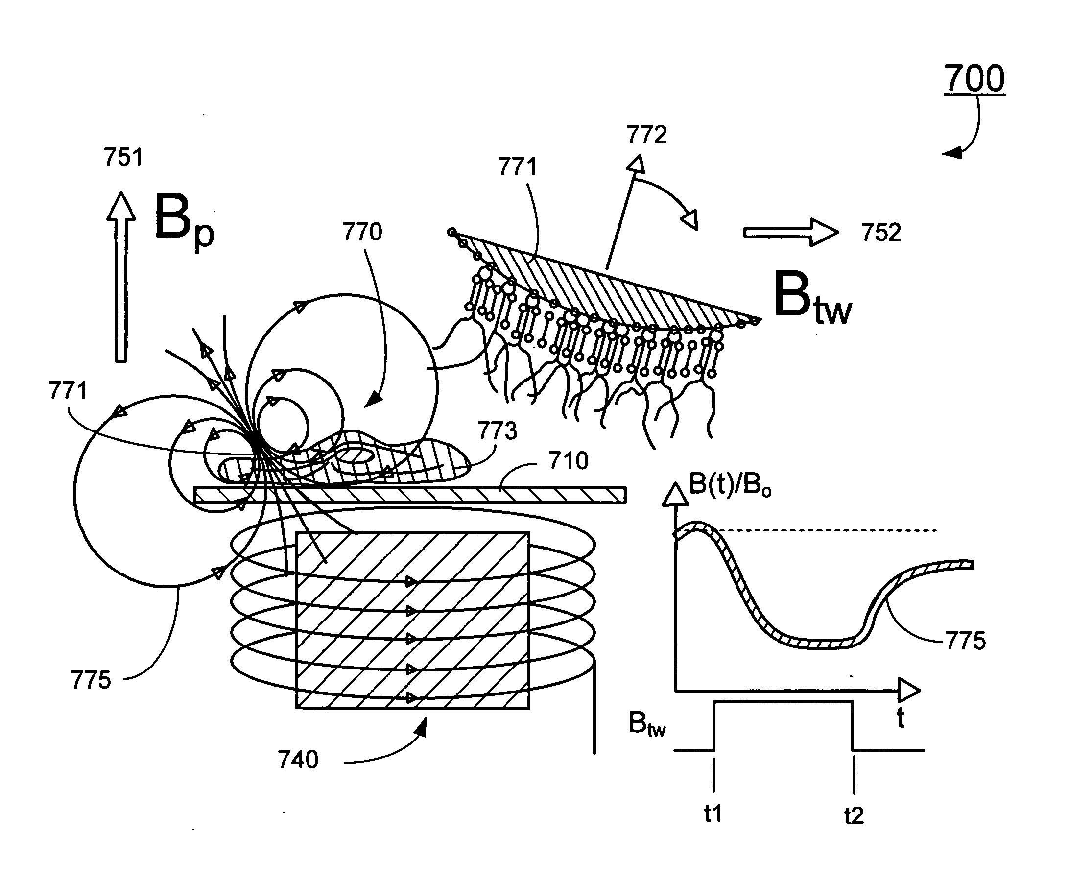
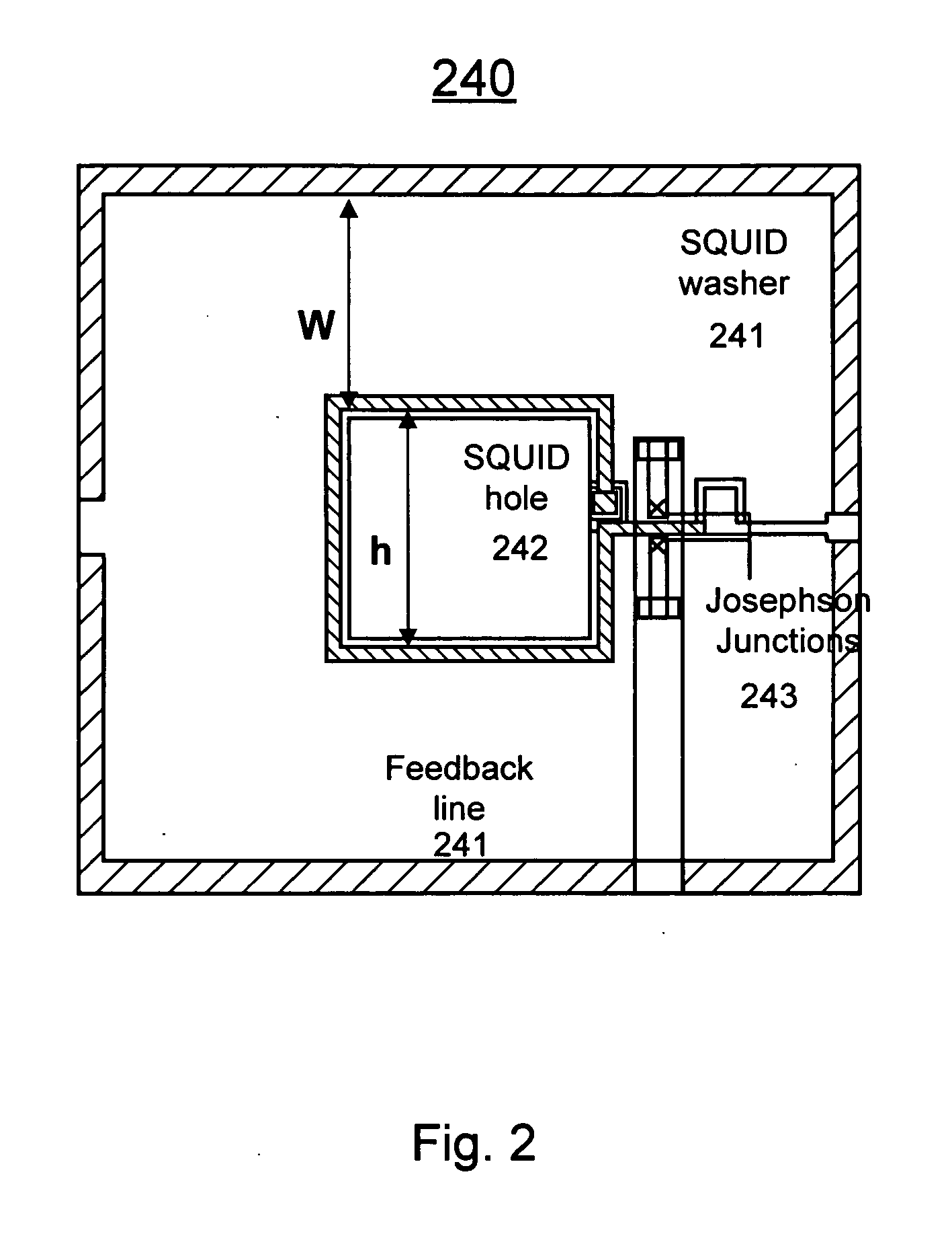
[0028] In one aspect, the present invention relates to a vector microscope. In one embodiment, the vector microscope has three orthogonally oriented SQUID sensors, where the three SQUID sensors are mounted onto a tip of a sapphire cube, where in operation, the sapphire cube is diagonally aligned normal to a scanning plane. In one embodiment, the SQUID sensor comprises a directly-coupled low-temperature niobium based SQUID sensor. In another embodiment, the SQUID sensor comprises a washer-type SQUID sensor characterized with a SQUID inductance, L, a Josephson junction (JJ) critical current, Ic, a JJ self-capacitance, C, and a shunt resistance, Rn, where the SQUID sensor is adapted such that when the SQUID operates at a temperature of about 4.2 K, the SQUID inductance L, the JJ critical current Ic, the JJ self-capacitance C, and the shunt resistance Rn satisfy the relationships of βc=2πIcRn2C/φ0≦0.7 and βL=2LIc/φ0≅1, where φ0 is a flux quantum of about 2×10⁻¹⁵ Wb.
[0029] In another aspect, the present invention relates to a method of probing the mechanical properties and cell motility of single cells. In one embodiment, the method includes the steps of: (a) providing a cell sample containing cells and magnetic beads, each magnetic bead attached to a corresponding cell to form a cell-bead unit such that when the magnetic bead moves and/or rotates, the corresponding cell moves and/or rotates accordingly; (b) providing a microfluidic structure defining a detecting zone capable of trapping a single cell therein; (c) providing a vector microscope positioned proximately t

Problems solved by technology

Typically separation techniques can not discriminate according to the magnetic moment and can only isolate magnetically tagged analytes from their non-magnetic counterparts.
However, in applications like flow cytometer it is

Method used


Image

  • Magnetic flow cytometer with SQUID microscopy
  • Magnetic flow cytometer with SQUID microscopy
  • Magnetic flow cytometer with SQUID microscopy

Examples


Embodiment Construction

[0041] The present invention is more particularly described in the following examples that are intended as illustrative only since numerous modifications and variations therein will be apparent to those skilled in the art. Various embodiments of the invention are now described in detail. Referring to the drawings, like numbers indicate like parts throughout the views. As used in the description herein and throughout the claims that follow, the meaning of “a,”“an,” and “the” includes plural reference unless the context clearly dictates otherwise. Also, as used in the description herein and throughout the claims that follow, the meaning of “in” includes “in” and “on” unless the context clearly dictates otherwise. Moreover, titles or subtitles may be used in the specification for the convenience of a reader, which has no influence on the scope of the invention. Additionally, some terms used in this specification are more specifically defined below.

Definitions

[0042] The terms used in ...


PUM


Abstract

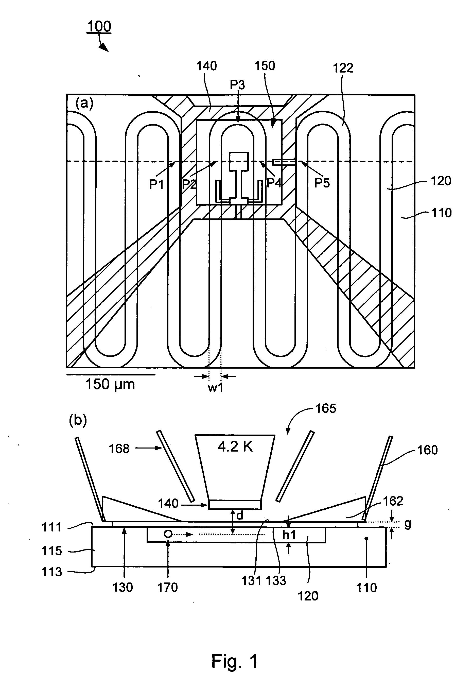
A flow cytometer. In one embodiment, the flow cytometer has a microfluidic structure defining a channel with a periodically modulated path for transporting a stream of fluid with magnetic particles along the modulated path, and a superconducting quantum interference device (SQUID) sensor positioned over the microfluidic structure to define a detecting zone in the microfluidic structure for detecting magnetic signatures of a magnetic particle passing along the periodically modulated path through the detecting zone, where in use the stream of fluid with magnetic particles is regulated such that each magnetic particle passes singly along the periodically modulated path through the detecting zone.

Description

CROSS-REFERENCE TO RELATED PATENT APPLICATION [0001] This application claims the benefit, pursuant to 35 U.S.C. §119(e), of U.S. provisional patent application Ser. No. 60 / 738,814, filed Nov. 22, 2005, entitled “A MAGNETIC FLOW CYTOMETER WITH SQUID MICROSCOPY,” by Franz Baudenbacher, Luis E. Fong, Eduardo Andrade Lima, David K. Schaffer, and John Wikswo, which is incorporated herein by reference in its entirety. [0002] Some references, which may include patents, patent applications and various publications, are cited and discussed in the description of this invention. The citation and / or discussion of such references is provided merely to clarify the description of the present invention and is not an admission that any such reference is “prior art” to the invention described herein. All references cited and discussed in this specification are incorporated herein by reference in their entireties and to the same extent as if each reference was individually incorporated by reference. I...

Claims


Application Information

Patent Timeline
IPC IPC(8): A61B5/05
CPCG01R33/0354G01N33/54333
Inventor BAUDENBACHER, FRANZFONG, LUIS E.LIMA, EDUARDO ANDRADESCHAFFER, DAVID K.WIKSWO, JOHN
Owner VANDERBILT UNIV
Why Eureka
Try Eureka