Superconducting switching amplifier

a switching amplifier and superconducting technology, applied in the direction of pulse generator, pulse generator, electric pulse generator circuit, etc., can solve the problems of not well defined output condition of resistive state, inability to switch squid from resistive state to superconductive state, and inconvenient operation of resistive state, etc., to achieve selectively raised or lowered

Inactive Publication Date: 2008-02-28
HYPRES
View PDF20 Cites 29 Cited by
  • Summary
  • Abstract
  • Description
  • Claims
  • Application Information

AI Technical Summary

Benefits of technology

[0013] A superconducting switching amplifier embodying the invention includes superconductive means responsive to input signals for clamping the output of the amplifier to a first voltage or to a second voltage. The amplifier includes first and second voltage lines for the respective application thereto of first (V1) and second (V2) different voltages. A first set of superconducting devices is serially connected between the first voltage line and an output terminal. A second set of superconducting devices is serially connected between the output terminal and the second voltage line. The devices comprising the first and second set of devic...

Problems solved by technology

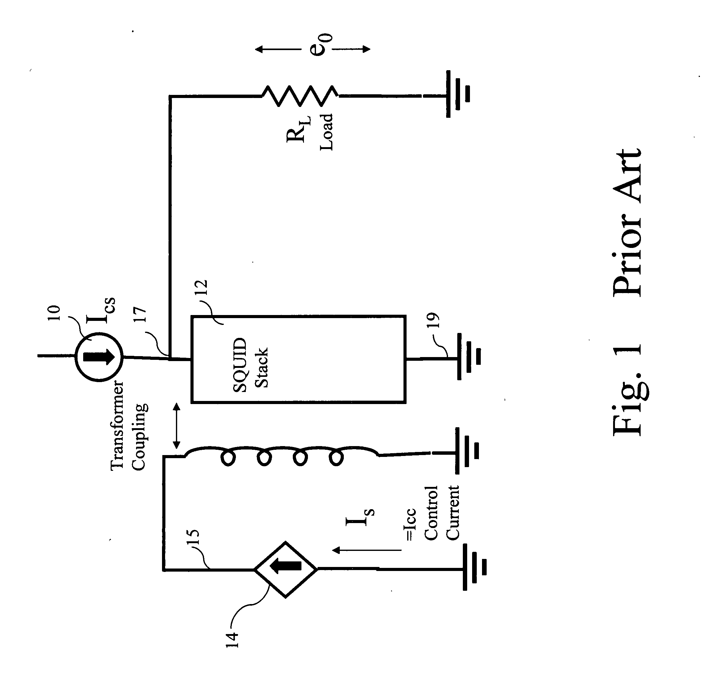
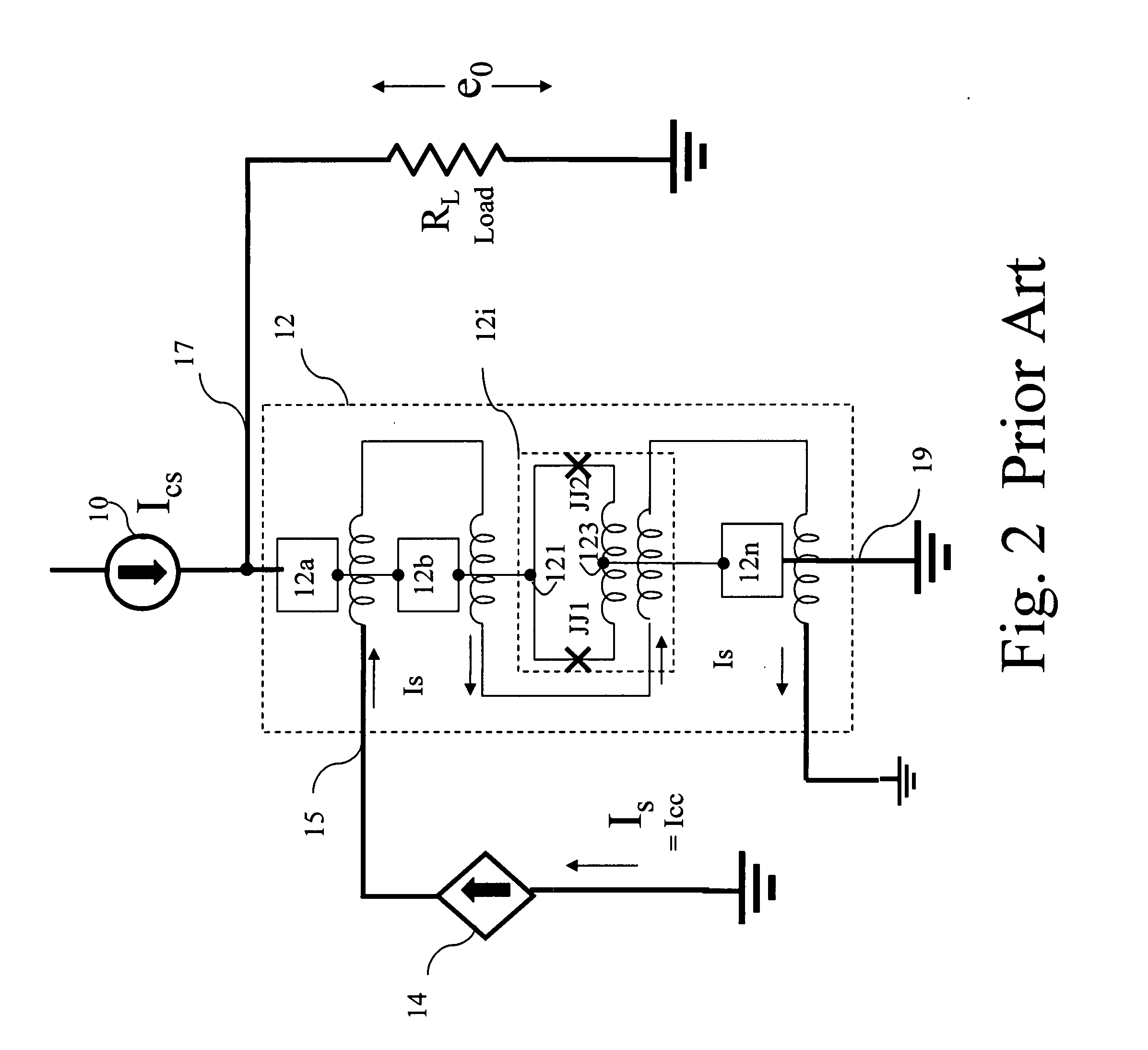
However, the prior art circuit suffers from some significant limitations in that the output for the resistive state condition is not well defined.
However, if Ics is made greater than some value of Ich, the SQUID can not be readily switched from the resistive state to superconductive state.
Thus, the prior art circuit provides for a degree of signal amplification, but does not ensure that the output signal is driven to a known and fixed voltage level when the SQUIDs in the stack are in the resistive state.
The stack of SQUIDS cannot be driven by a voltage source because of the short circuit condition which would cause undesirably large currents...

Method used


Image

  • Superconducting switching amplifier
  • Superconducting switching amplifier
  • Superconducting switching amplifier

Examples


Embodiment Construction

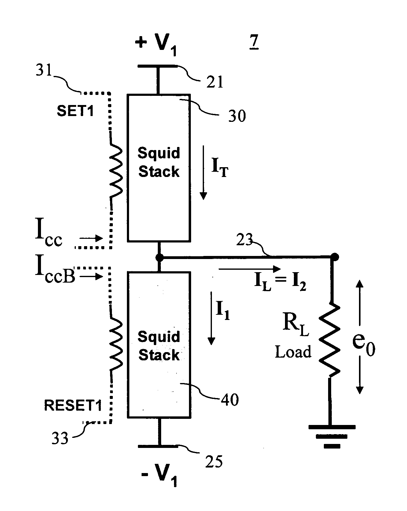
[0038] Referring to FIG. 4, there is shown an amplifier 7 comprised of a first SQUID stack 30 and a second SQUID stack 40. SQUID stack 30 is connected between a first voltage line 21 and on output terminal 23 and SQUID stack 40 is connected between output terminal 23 and a second voltage line 25. In FIG. 4, a voltage (+)V1 is applied to line 21 and a voltage of (−)V1 is applied to line 25. A control line 31 for controlling the critical current (Ic) level of SQUID stack 30 is formed to extend and wind about the SQUIDs of stack 30 and a control line 33 for controlling the critical current level of SQUID stack 40 is formed to extend and wind about the SQUIDs of stack 40. A load resistor RL is shown connected between output line 23 and a point of reference potential (i.e., ground, but another suitable voltage between +V1 and −V1 could be used instead).

[0039] Complementary input signals, denoted as Icc (also SET 1) and IccB (also RESET 1), are respectively applied to control lines 31 an...


PUM


Abstract

A superconducting switching amplifier embodying the invention includes superconductive devices responsive to input/control signals for clamping the output of the amplifier to a first voltage or to a second voltage. The amplifier includes a first set of superconducting devices serially connected between a first voltage line and an output terminal and a second set of superconducting devices serially connected between the output terminal and a second voltage line. The first set and the second set of devices are operated in a complementary fashion in response to control signals. When one of the first and second sets is driven to a superconducting (zero resistance) state the other set is driven to a resistive state. In accordance with the invention, the devices of each set are laid out in a pattern and driven in a manner to enable all the devices of each set to be driven to a selected state at substantially the same time. In one embodiment, the devices in each set are superconducting quantum interference devices (SQUIDs). Four sets of superconductive devices may be interconnected to function as a differential switching amplifier. The operating voltage applied to an amplifier may be varied to provide additional shaping of the output signal.

Description

[0001] This invention claims priority based on Provisional Application Ser. No. 60 / 840,379 filed Aug. 25, 2006 and titled “Techniques for Processing Multi-GHz Frequency Signals”.[0002] This invention was developed in part under Army SBIR Contract W15P7T-04-C-K-403.BACKGROUND OF THE INVENTION [0003] This invention relates to superconducting circuits employing devices such as those known as Josephson junctions (JJs). [0004] It is known in the art to employ JJs integrated together according to a rapid-single flux-quantum (RFSQ) methodology to manufacture ultrafast superconducting digital circuits. [0005] The RSFQ technology is a low-voltage technology producing pulses having amplitudes in the range of 0.5 millivolts (mV) which are very fast (e.g., 4 picoseconds wide). In order to transmit the digital information generated by and within these RSFQ circuits for processing by standard semiconductor circuits, several stages of amplification are needed to increase the amplitude of the pulse...

Claims


Application Information

Patent Timeline
IPC IPC(8): H03K3/38
CPCH03F3/217H03K17/92H03K5/02H03F19/00
Inventor INAMDAR, AMOL A.RYLOV, SERGEY V.
Owner HYPRES
Why Eureka
Try Eureka