Computer system, computer system management console, and data recovery management method

a technology of computer system and management console, applied in the field of computer system management console, data recovery management method, can solve problems such as data image and inability to be recovered

Inactive Publication Date: 2007-08-23
HITACHI LTD
View PDF9 Cites 53 Cited by
  • Summary
  • Abstract
  • Description
  • Claims
  • Application Information

AI Technical Summary

Benefits of technology

[0013] This invention can provide a computer system able to recover data at an arbitrary point in time by using a journal even after a data volume has been migrated between storage apparatuses; a management computer used for the computer system; and a method for recovering data.

Problems solved by technology

When recovering a data volume in this situation, the storage apparatus executing the recovery (hereinafter called ‘recovery-executing storage apparatus’) cannot access the snapshots and journals necessary for the recovery, and the data image at an arbitrary point in time may not be recovered.

Method used


Image

  • Computer system, computer system management console, and data recovery management method
  • Computer system, computer system management console, and data recovery management method
  • Computer system, computer system management console, and data recovery management method

Examples


first embodiment

1. System Configuration

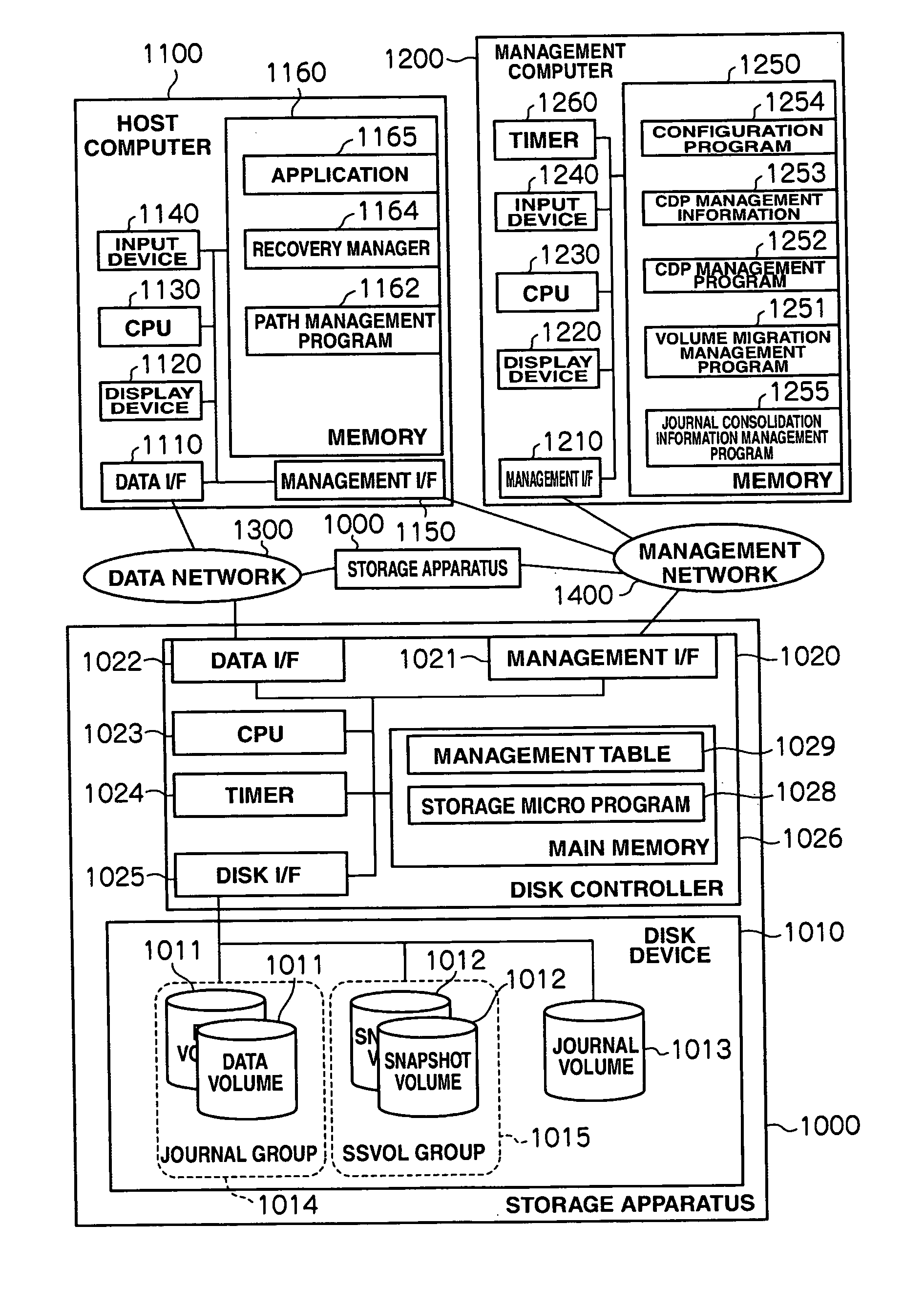
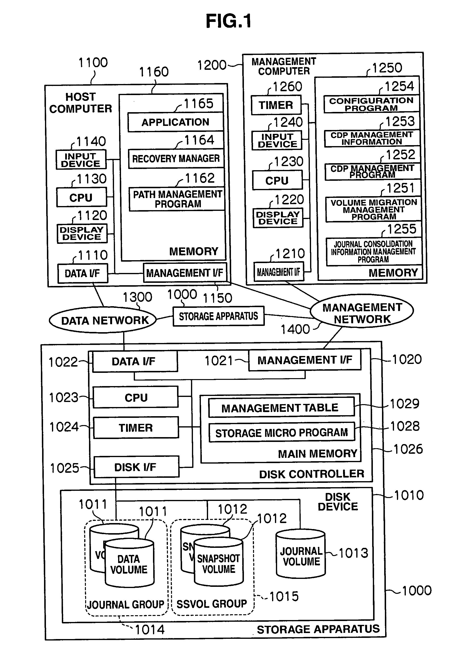
[0043]FIG. 1 is a block diagram showing the configuration of a computer system. A storage apparatus 1000 and a host computer 1100 are connected to each other via a data network 1300. The data network 1300, which is a storage area network, may be an IP network or other data communication network(s).

[0044] The storage apparatus 1000, host computer 1100 and management computer 1200 are connected to one another via a management network 1400. The management network 1400, which is an IP network, may also be a storage area network or other data communication network(s). The data network 1300 and management network 1400 may be part of the same network, and the host computer 1100 and management computer 1200 may also be part of the same computer. Although the system shown in FIG. 1 has two storage apparatuses 1000, one host computer 1100 and one management computer 1200, the number of these devices is not limited.

[0045] The storage apparatus 1000 has a disk device ...

second embodiment

[0152] The second embodiment of this invention is explained next. In this embodiment, a first storage apparatus virtualizes a volume of an external storage apparatus using the external connection function and uses it in its own apparatus as a data volume (‘hereinafter called virtual data volume’) constituting a journal group. In such a configuration, the same volume in the external storage apparatus is also externally connected to a second storage apparatus, which creates a virtual data volume so that the virtual data volume can be migrated between the storage apparatuses. However, in this case, there is a problem in that journals and snapshots related to the virtual data volume are distributed among the storage apparatuses, which disables recovery using journaling. The second embodiment is used to explain that this invention can be applied to such a configuration.

1. System Configuration in the Second Embodiment

[0153]FIG. 19 is a block diagram showing the configuration of the stor...

third embodiment

[0173] The third embodiment of this invention is explained next. This embodiment adopts the configuration where, in addition to a data volume constituting a journal group being a virtual volume (virtual data volume), a snapshot volume constituting an SSVOL group, and a journal volume are also virtual volumes. In the following description, a virtual volume serving as a snapshot volume is called a virtual snapshot volume, and a virtual volume serving as a journal volume is called a virtual journal volume.

1. System Configuration in the Third Embodiment

[0174]FIG. 23 is a block diagram showing the configuration of a storage apparatus. The greater part of this configuration is the same as that in the second embodiment, so only the differences will be explained below. In a storage apparatus 1000, an SSVOL group 1015 is not composed of a snapshot volume 1012 but from a virtual snapshot volume 1017. This virtual snapshot volume 1017 is a volume formed by virtualizing a logical volume 1516 ...


PUM


Abstract

A computer system that is able to recover data at an arbitrary point in time using journals even after a data volume has been migrated between storage apparatuses. The computer system has a data recovery management unit create continuous journal data that ensures the continuity of journals before and after the migration of the data volume and, based on that continuous journal data, recovers the data.

Description

CROSS REFERENCES TO RELATED APPLICATIONS [0001] This application relates to and claims priority from Japanese Patent Application No. 2006-044416, filed on Feb. 21, 2006, the entire disclosure of which is incorporated herein by reference. BACKGROUND OF THE INVENTION [0002] The present invention relates to a computer system where a host computer is connected to a storage apparatus, with a management console for managing the storage apparatus also included; a management console for the computer system; and a recovery management method for data in the computer system. [0003] Normally, in information systems having storage apparatuses, when data is lost due to the occurrence of a failure in the storage apparatuses, user error or data destruction by computer viruses, the lost data can be recovered because data volumes are backed up on a regular basis. [0004] As backup and recovery techniques, data backup and recovery techniques using journaling have been proposed in, for example, US Paten...

Claims


Application Information

Patent Timeline
Patent Type & Authority Applications(United States)
IPC IPC(8): G06F17/30
CPCG06F17/30893G06F16/972
Inventor OKADA, WATARUSATO, MASAHIDEEMARU, HIRONORIMAKI, NOBUHIROHIRAIWA, YURI
Owner HITACHI LTD
Why Eureka
Try Eureka