Apparatus and method for machining long workpiece

a technology of machining apparatus and workpiece, which is applied in the direction of auxilary equipment, workpiece holders, manufacturing tools, etc., can solve the problems of difficult to machine the held portions, and the inability to machining at least in automatic operation

Active Publication Date: 2007-08-30
IMAX CO LTD
View PDF7 Cites 47 Cited by
  • Summary
  • Abstract
  • Description
  • Claims
  • Application Information

AI Technical Summary

Benefits of technology

[0020] The present invention has been developed in order to solve these problems. That is, an object of the present invention is to provide a machining apparatus and method for a long workpiece, wherein no exclusive-use jigs that match an irregular shape are needed even if the workpieces have continuous-lengths and irregular shapes, the workpieces do not need to be rotated in the reverse direction even when the entire periphery of the long workpiece is machined, no extra space is needed to convey the long workpiece in and out, and the held portions of the long workpiece can be automatically machined, whereby machining of a continuous-length, irregularly shaped workpiece can be automated other than at times during which the workpieces are being conveyed in or out.
[0056] Also, un-notched cylindrical rings are supported so as to be capable of rotating around the horizontal axis O. Therefore, the rings can rotate 360°, and the machined object does not need to be rotated in the opposite direction even in cases in which the entire peripheral surface of the long workpiece is machined.

Problems solved by technology

(4) With the apparatuses in Patent Documents 1 through 4, the held portions of the workpieces interfere with the holding devices and the machining apparatus, making it difficult to machine the held portions as such, and making machining impossible at least in automatic operation.

Method used


Image

  • Apparatus and method for machining long workpiece
  • Apparatus and method for machining long workpiece
  • Apparatus and method for machining long workpiece

Examples


Embodiment Construction

[0070] Preferred embodiments of the present invention will be described hereinafter with reference to the drawings. Additionally, common portions are denoted with the same reference numerals in the respective drawings, and redundant description is omitted.

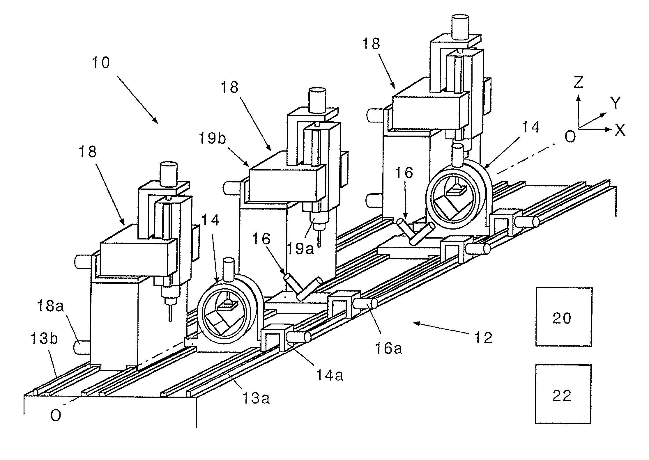
[0071]FIG. 5 is a whole perspective view of the machining apparatus of long workpiece according to the present invention. The long workpiece machining apparatus 10 is a machining apparatus for machining long workpiece (not shown) while rotating the workpiece around the center of a horizontal axis O extending in the length direction of the long workpiece, which has a constant sectional shape. The long workpiece machining apparatus 10 comprises a base frame 12, a pair of clamp units 14, a pair of support units 16, and one ore more machining units 18.

[0072] The base frame 12 is positioned below the horizontal axis O and extends along the horizontal axis O. Backlash-free rack and pinion mechanisms, e.g., trochoid cam gear runners 13a...


PUM

PropertyMeasurementUnit
angleaaaaaaaaaa
lengthaaaaaaaaaa
rotational anglesaaaaaaaaaa

Abstract

There are provided a base frame 12 positioned below a horizontal axis O; a pair of clamp units 14 positioned at the two ends above the base frame; a pair of support units 16 that horizontally support the long workpiece in two locations, and that are capable of moving vertically; and machining units 18 that are capable of machining the long workpiece. The two clamp units 14 are capable of moving from the outside toward the inside, which support the long workpiece in two locations, and rotate around the horizontal axis O in synchronization with each other.

Description

BACKGROUND OF THE INVENTION [0001] 1. Technical Field of the Invention [0002] The present invention relates to a machining apparatus and method for machining long workpiece having a constant sectional shape. [0003] 2. Description of the Related Art [0004] Various workpieces of continuous lengths, which have constant section shape, have been used as general building workpieces such as an aluminum sash. In this application such workpieces of continuous lengths are referred as “long workpieces”. [0005] Patent Documents 1 and 2 disclose examples of apparatuses that process long workpieces such as I-beams and H-section steel. [0006] The rotatable handling device in Patent Document 1 is constituted of positioning units 50, 51 for supporting the proximities of the ends of an I-beam 54, as shown in FIG. 1. The positioning unit 50 is attached to the top of a driving roller unit 53. The positioning unit 51 is attached to the top of a driven roller unit 54 that is in contact with the driving r...

Claims


Application Information

Patent Timeline
Patent Type & Authority Applications(United States)
IPC IPC(8): B23B27/00B23P23/00
CPCB23C3/002B23Q1/527B23Q7/042B23Q39/023Y10T82/2597Y10S269/902Y10T409/305656Y10T409/307168Y10T82/2593Y10T409/305768Y10T29/5114B23Q2240/007
Inventor OHMORI, HITOSHIMITSUISHI, NORIHIDEMIURA, TAKAHIROIWAMITSU, NAOSHI
Owner IMAX CO LTD
Why Eureka
Try Eureka