Height adjustment system for image forming machine

a technology of height adjustment and image forming machine, which is applied in the direction of typewriters, printing, power drive mechanisms, etc., can solve the problems of colorant smearing on the substrate, colorant stretching, and colorant bleeding,

Inactive Publication Date: 2007-08-30
YUHAN KIMBERLY LTD
View PDF27 Cites 5 Cited by
  • Summary
  • Abstract
  • Description
  • Claims
  • Application Information

AI Technical Summary

Benefits of technology

[0008] The inventors have found that vertically adjusting the height of the continuous substrate feeding system instead of moving the printing head unit, allows for a greater range of adjustment with less opportunity to damage the printing head unit. This allows for a wider range of substrates of much greater thickness to be printed upon.

Problems solved by technology

The shear size of the image forming machine used in wide-width printing presents the user with a variety of technical problems.
Existing substrate feeding systems, for example, can result in substrate stretching, misalignment, wrinkling, and colorant bleeding as the substrate is feed over plates and between pinch rolls during the printing process.
Improper drying of the substrate can result in smearing of the colorant on the substrate or on parts of the image forming machine.
In addition, current systems also have difficulty in adapting to substrates of varying thicknesses.
Current image forming machines are able to adapt to variations in substrate thickness of up to about 1 mm from the machine's built in or pre-set thickness capability because the printing head is moved vertically to accommodate thicker substrates while the balance of the machine is held stationary, and the range of this movement is limited.
The complexity of these image forming machines presents another challenge to the designer as modifications and changes to existing systems must be capable of fitting into relatively small spaces.
In addition, certain types of printing heads are quite fragile and must be treated with the utmost care lest they be damaged.
The close tolerances required in the making of such machines allow for the creation of high quality images, but make successful modification of the machine quite difficult.

Method used


Image

  • Height adjustment system for image forming machine
  • Height adjustment system for image forming machine
  • Height adjustment system for image forming machine

Examples


Embodiment Construction

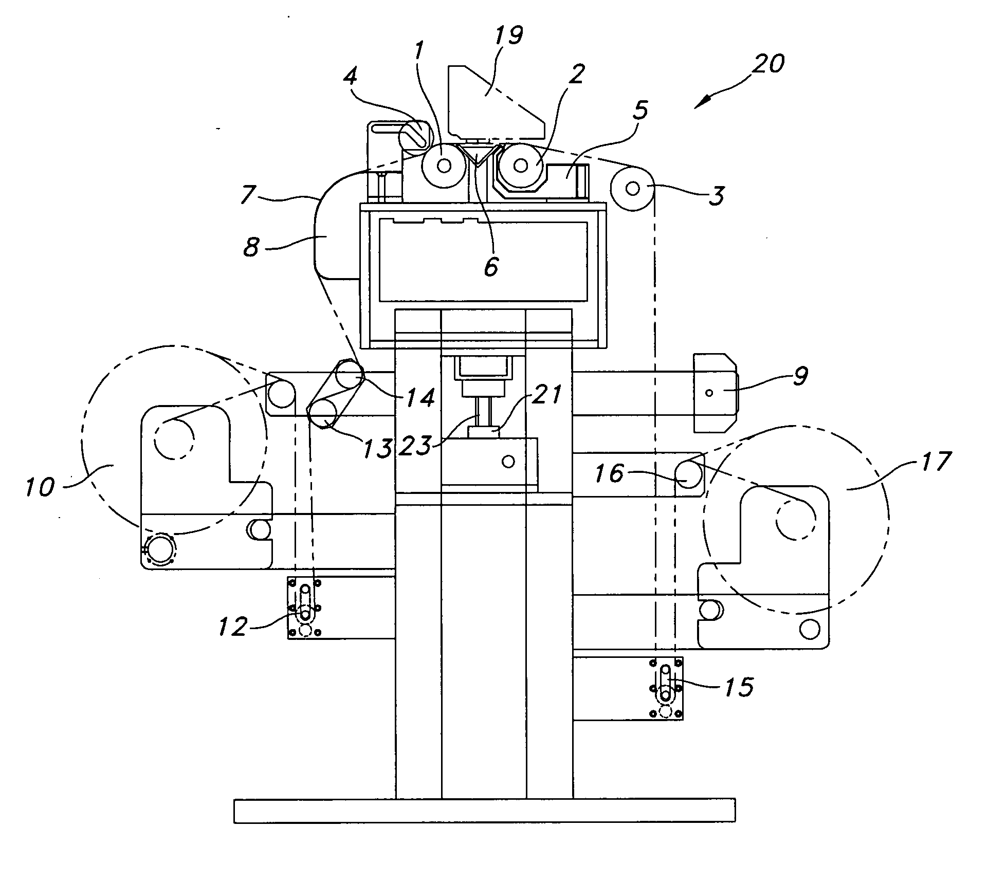
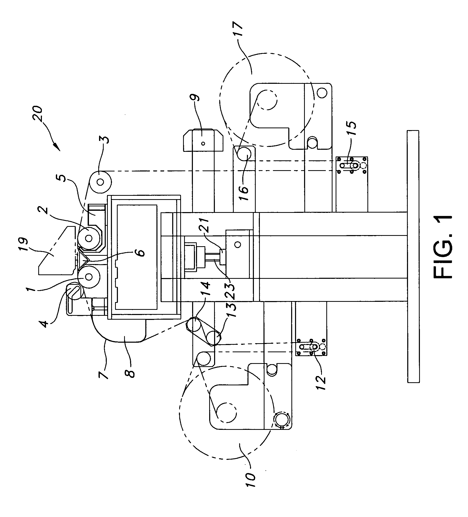
[0010] Turning to FIG. 1 one can see that the substrate feeding system 20 of the image forming machine includes at least two feeder rolls (1, 2) and a third feeder roll 3, as well as a press roll 4 arranged around an ink tray 6 located in the printing zone. The printing zone is the area where the printing head unit 19 travels perpendicularly to the direction of movement of the substrate (the machine direction or MD). FIG. 1 shows the invention in the X and Y planes and the movement of the printing head is in the Z direction (the cross-machine direction or CD). The printing head unit is mounted to a frame support system (not shown) which is independent of the support for the substrate feeder system.

[0011] The substrate 7 is taken from a supply roll 10 around various guide rollers 11 and around a rack and pinion roll 12, though this may vary based on the needs of the user. The rack and pinion roll 12 serves as one means of controlling tension by moving vertically as needed in respons...


PUM


Abstract

There is provided a feeding system for an image forming machine using a first feeder roll and a press roll that form a nip between them though which a substrate is passed, and a second feeder roll located after a printing zone, where the first and second feeder rolls move at the same speed.

Description

BACKGROUND OF THE INVENTION [0001] Wide format image forming machines are used for printing complex patterns on various substrates like paper, films, nonwoven fabrics, woven cotton, canvas, silk, polyester, nylon, Lycra® and other materials. These printers or image forming machines are capable of producing images on substrates having widths of greater than about 36 inches (910 mm) at relatively high speeds. Such large scale applications include the creation of images on mattress covers and bedspreads, automotive fabrics, upholstery, architectural applications, signs and banners and the like. [0002] Wide format image forming machines generally have a plurality of printing heads mounted above the substrate and move across the substrate, perpendicular to the direction of motion of the substrate. As the printing heads move from side to side across the substrate, they deposit colorant to form an image in a predetermined pattern, conventionally controlled by a computer system. [0003] The ...

Claims


Application Information

Patent Timeline
Patent Type & Authority Applications(United States)
IPC IPC(8): B41J25/308
CPCB41J3/4078B41J11/001B41J29/02B41J15/04B41J11/20
Inventor PARK, NAMJEONMOON, YUNJOOKIM, DONGMINOH, JUNGMIKYUN, BYUNGCHULMOON, SOONJAELEE, JUNHO
Owner YUHAN KIMBERLY LTD
Why Eureka
Try Eureka