Thin Film Interference Filter and Bootstrap Method for Interference Filter Thin Film Deposition Process Control

a thin film deposition process and interference filter technology, applied in the field of complex interference filters, can solve the problems of large amount of optical dielectric, and large amount of optical dielectric, and achieve the effect of uniform, or otherwise undesirable passband of bulk materials, avoiding the formation of a single, or avoiding the formation of a single, or avoiding the formation of a single, or

Inactive Publication Date: 2007-08-30
HALLIBURTON ENERGY SERVICES INC
View PDF5 Cites 35 Cited by
  • Summary
  • Abstract
  • Description
  • Claims
  • Application Information

AI Technical Summary

Benefits of technology

The present invention is about a way to make a layered, thin film interference filter. It uses a method called bootstrap to estimate the properties of the filter as layers are deposited. This method allows the user to focus on a single layer and ignore errors in the rest of the film stack. By fitting the single-layer model to the observed spectra of the film stack, the remaining layers can be accurately updated for continued deposition. The technical effect is that it provides a way to make filters with greater accuracy and efficiency.

Problems solved by technology

The patent text discusses the manufacturing of thin film interference filters, which can be used for optical computing and other applications. However, current methods have limitations in accurately modeling the detailed structure of the film stack and the resulting spectra can be affected by small variations in deposition conditions. The technical problem addressed in the patent text is to create a thin film interference filter that is easier to manufacture and has precise rejection bands and passbands.

Method used


Image

  • Thin Film Interference Filter and Bootstrap Method for Interference Filter Thin Film Deposition Process Control
  • Thin Film Interference Filter and Bootstrap Method for Interference Filter Thin Film Deposition Process Control
  • Thin Film Interference Filter and Bootstrap Method for Interference Filter Thin Film Deposition Process Control

Examples


Embodiment Construction

[0042] Detailed reference will now be made to the drawings in which examples embodying the present invention are shown. Repeat use of reference characters in the drawings and detailed description is intended to represent like or analogous features or elements of the present invention.

[0043] The drawings and detailed description provide a full and detailed written description of the invention and the manner and process of making and using it, so as to enable one skilled in the pertinent art to make and use it. The drawings and detailed description also provide the best mode of carrying out the invention. However, the examples set forth herein are provided by way of explanation of the invention and are not meant as limitations of the invention. The present invention thus includes modifications and variations of the following examples as come within the scope of the appended claims and their equivalents.

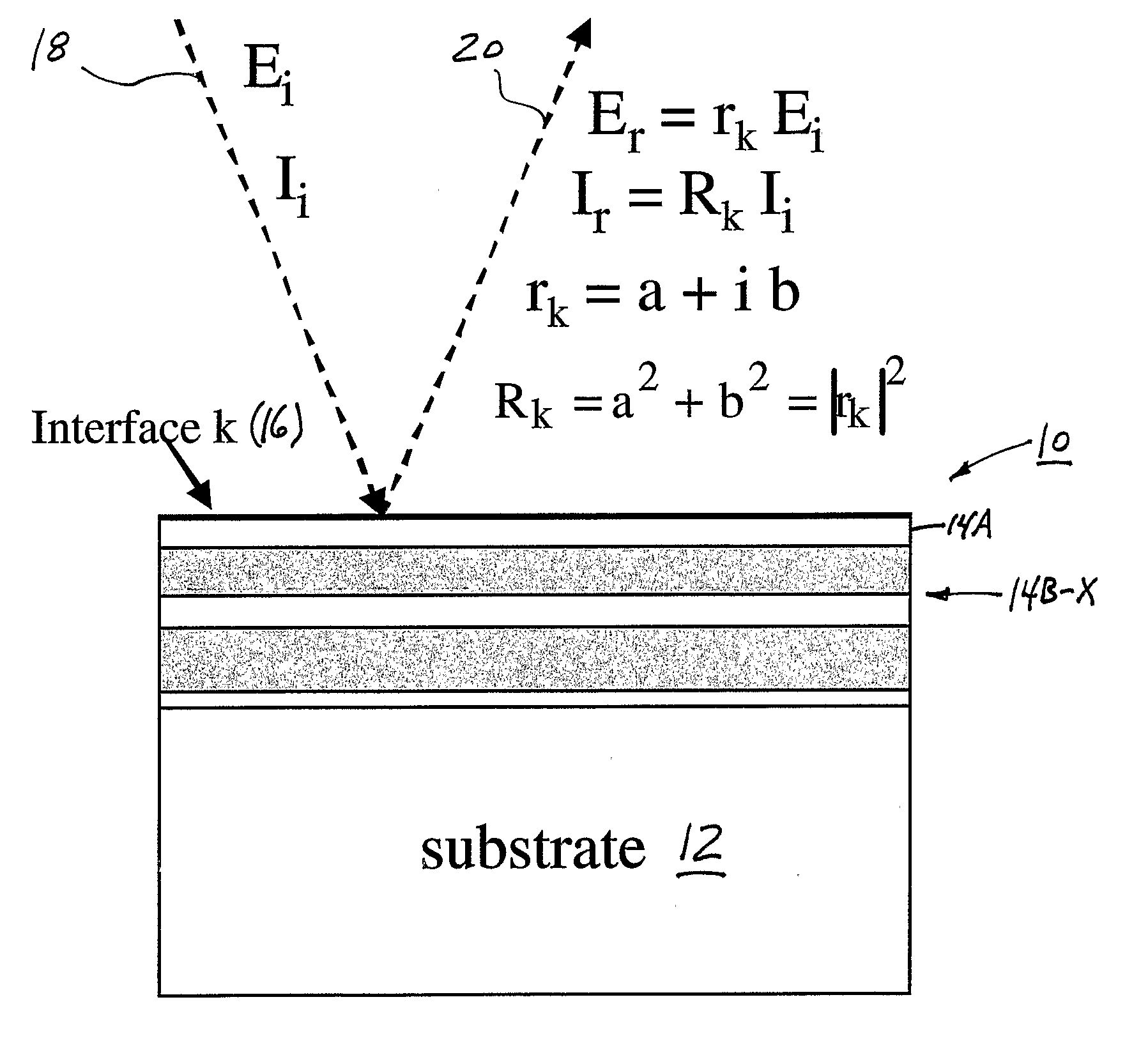
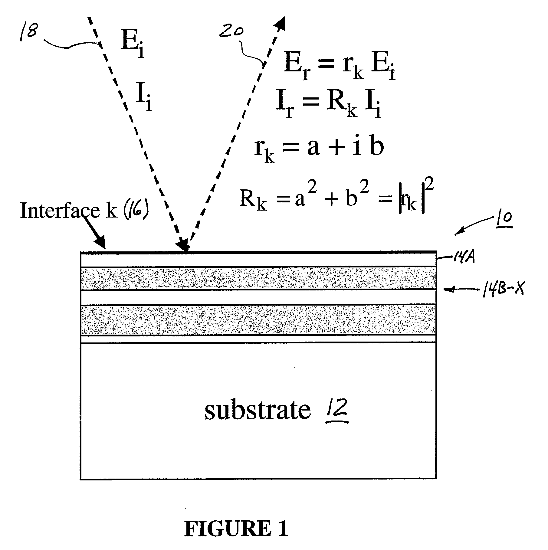
[0044] Turning now to the figures, FIG. 1 shows a thin film interference filter 1...


PUM


Abstract

A thin film interference filter system includes a plurality of stacked films having a determined reflectance; a modeled monitor curve; and a topmost layer configured to exhibit a wavelength corresponding to one of the determined reflectance or the modeled monitor curve. The topmost layer is placed on the plurality of stacked films and can be a low-index film such as silica or a high index film such as niobia.

Description


Claims


Application Information

Patent Timeline
Owner HALLIBURTON ENERGY SERVICES INC
Why Eureka
Try Eureka