System And Method For Vascular Visualization Using Planar Reformation Of Vascular Central Axis Surface With Biconvex Slab

a vascular central axis surface and planar reformation technology, applied in the field of systems and methods for vascular visualization, can solve the problems of lack of 3d information of the entire vessel, insufficient methods for visualizing vascular structures, and inability to accurately present calcification and stenosis, etc., to achieve efficient real-time processing and accurate presentation of calcification and stenosis

Inactive Publication Date: 2007-08-30
VIATRONIX
View PDF5 Cites 58 Cited by
  • Summary
  • Abstract
  • Description
  • Claims
  • Application Information

AI Technical Summary

Benefits of technology

[0010] Exemplary embodiments of the invention as described herein generally include systems and methods for vascular visualization using VPR (VCAS (vascular central axis surface) planar reformation) rendering techniques. More specifically, exemplary embodiments of the invention include systems and method for 3-D visualization of vascular structures using VPR rendering of 3D biconvex slab volumes to enable visualization of precise 3D spatial information of an entire vascular volume in one VPR image. Exemplary methods for vascular visualization using VPR rendering according to the invention provide efficient real-time processing of digital image data of vascular structures to accurately present calcification and stenosis.

Problems solved by technology

Although volume rendering is an accurate method for evaluating all grades of stenosis, in general these methods are inadequate to visualize vascular structures.
However, vascular abnormalities, such as stenosis and calcium, might not be scanned by this surface and therefore they do not appear in the generated image.
However, there is no 3D information on the images.
Traditional curved MPR forms a 2D image, and lacks the 3D information of the entire vessel.
However, a thin slab has some disadvantages for rendering VPR.
When the vessel has varying diameters, the thickness of the thin slab is difficult to control.
In addition, there are frequently obstructions that hide the views of the vascular lumen.
Second, the vessel centerline is often very long, resulting in a very long slab after stretching.
Thus, rendering a very long slab can become a time consuming task.
This image can visualize stenosis and calcification more clearly than normal curved MPR, but it is difficult to understand the 3D information from a helical CPR, such as the correct position and orientation of calcium and stenosis.
This difficulty is caused by the 2D image of CPR.
Other methods suffer from the ability to help a radiologist to find vascular abnormalities efficiently.

Method used


Image

  • System And Method For Vascular Visualization Using Planar Reformation Of Vascular Central Axis Surface With Biconvex Slab
  • System And Method For Vascular Visualization Using Planar Reformation Of Vascular Central Axis Surface With Biconvex Slab
  • System And Method For Vascular Visualization Using Planar Reformation Of Vascular Central Axis Surface With Biconvex Slab

Examples


Embodiment Construction

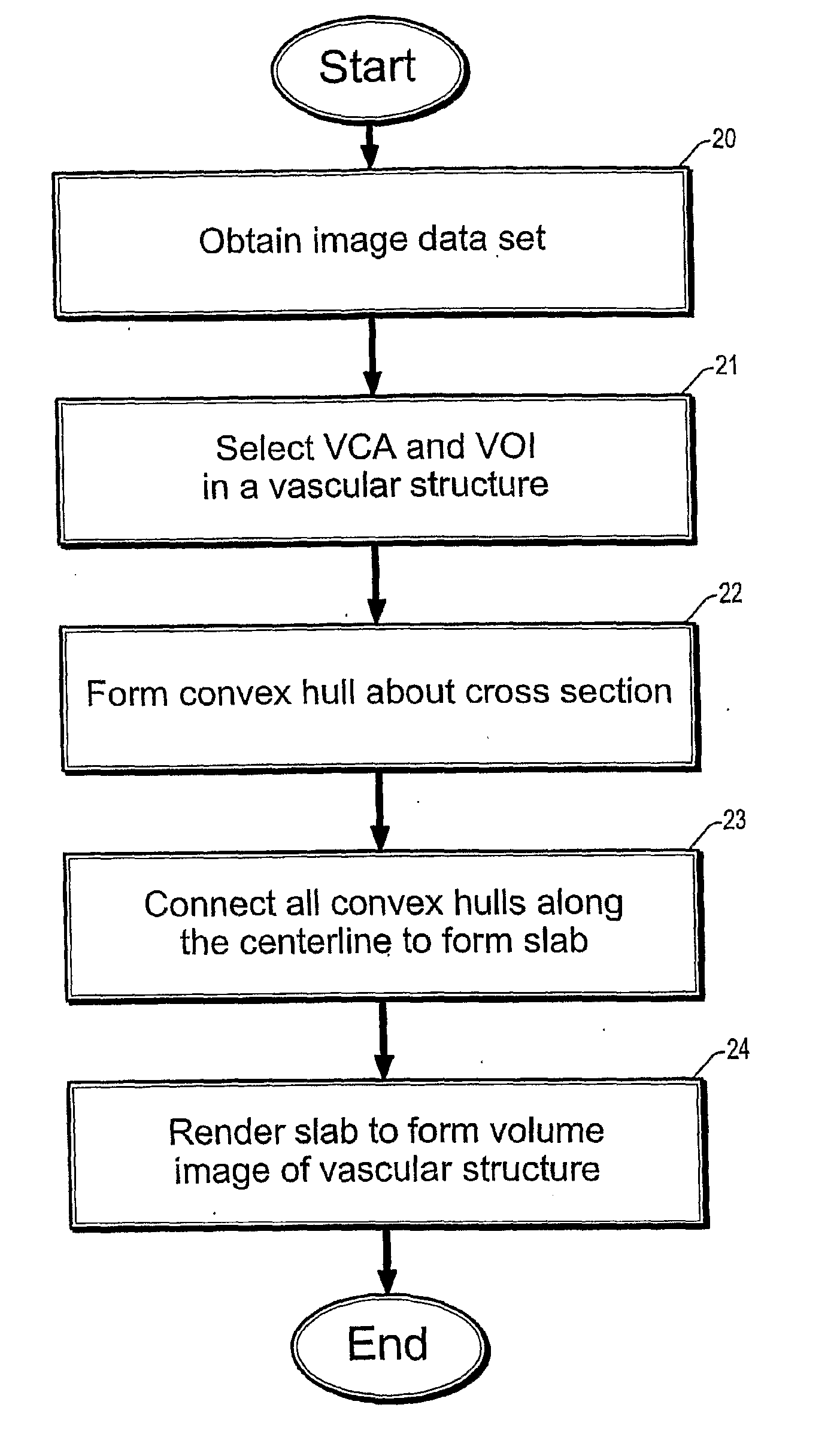
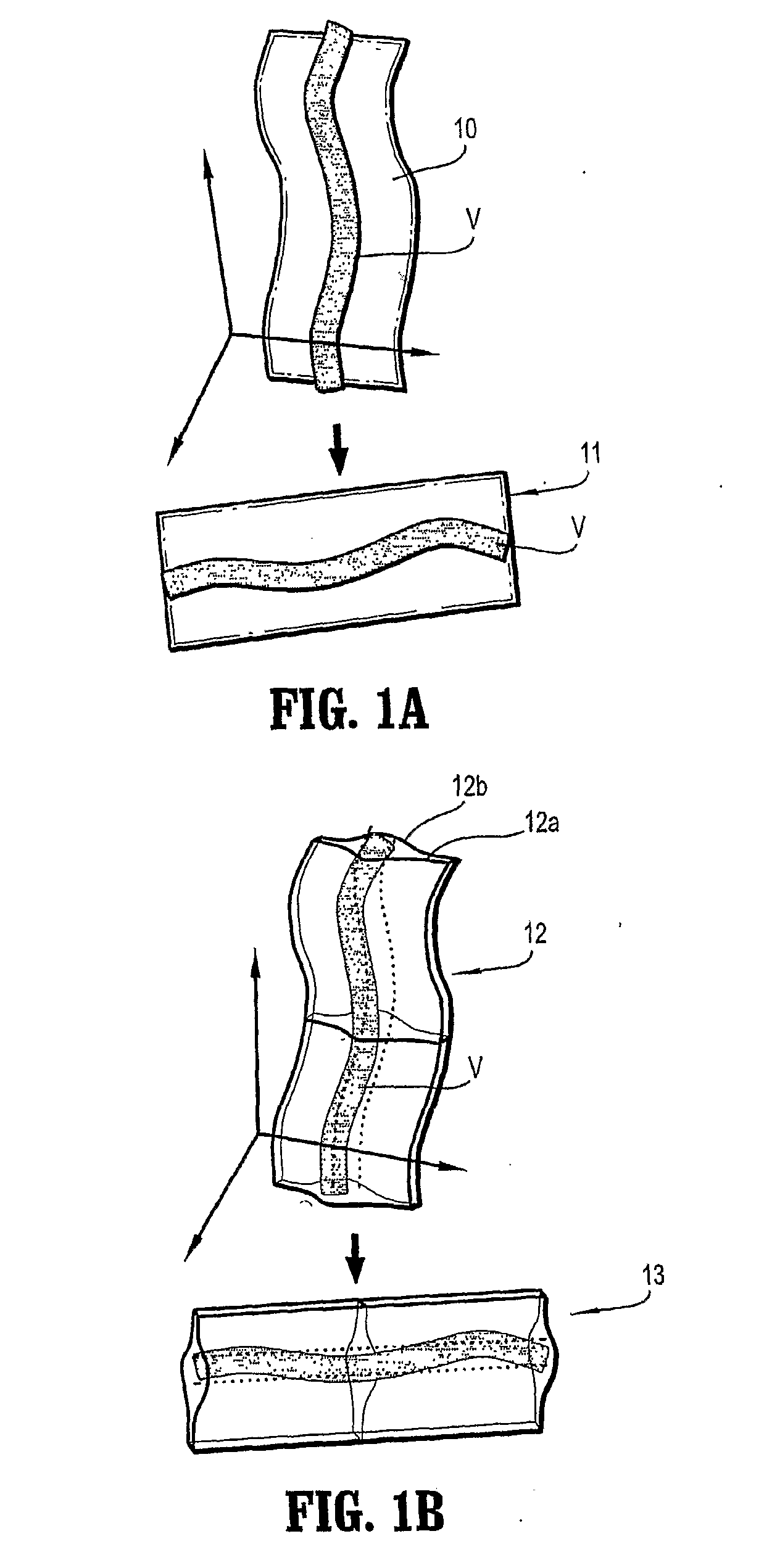
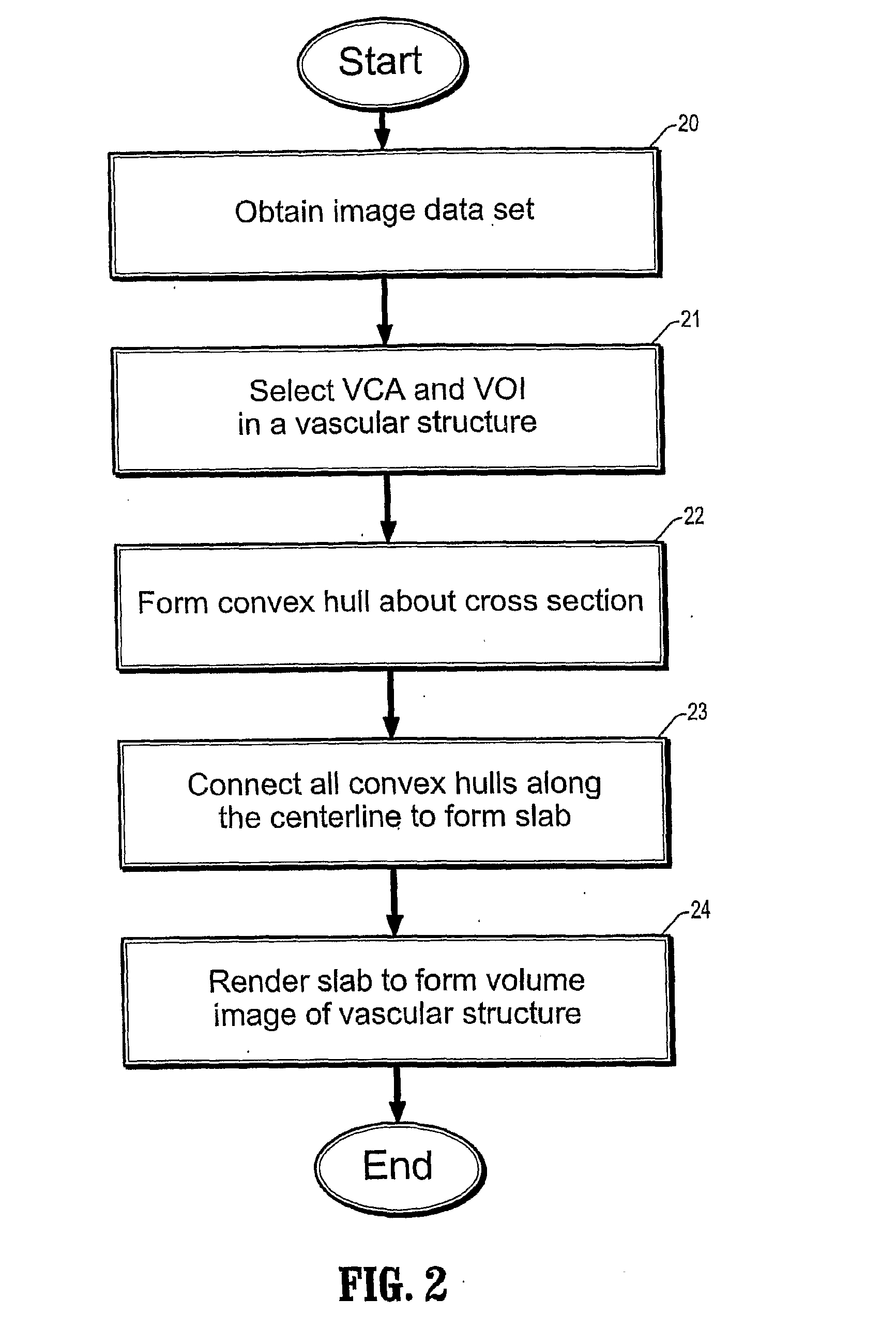
[0032] Exemplary embodiments of the invention include systems and methods for providing 3-D visualization of vascular structures using VPR rendering of 3D biconvex slab volumes to render precise 3D spatial information. Vascular visualization methods according to exemplary embodiments of the invention include methods for resampling image data within thick biconvex slab (as opposed to a thin 2D surface as with conventional methods) to enable fast and efficient visualization of an entire vascular volume in one image and minimize the obstructions from adjacent organs, such as bones. FIGS. 1A and 1B are exemplary diagrams that illustrate differences between conventional VPR rending and visualization methods and exemplary methods according to the invention.

[0033] In particular, FIG. 1A depicts a conventional vascular visualization process, wherein a vascular structure (V) is visualized by resampling a VCAS (vascular central axis surface) (10), which is a curved surface passing through a ...


PUM


Abstract

A method for visualizing a vascular structure includes obtaining an image dataset (step 20), selecting a vascular central axis (VCA) and a vector of interest (VOI) (step 21), forming a plurality of cross sections perpendicular to the vascular central axis, forming a convex hull to enclose each cross section (step 22), wherein the convex hull is oriented by the vector of interest and determined by the shape of the cross section, and connecting each convex hull to form a biconvex slab (step 23). The biconvex slab comprises two curved surfaces that enclose a 3D volume including the vascular structure 21 of interest. The volume within the biconvex slab can rendered to obtain a 3D view of the entire vascular structure (step 24). Since the biconvex slab is a 3D volume, volume rendering techniques can be used to render the 3D information and generate a resulting image of the vascular structure in a flattened plane having precise 3D spatial information.

Description

CROSS REFERENCE TO RELATED APPLICATION [0001] This application claims priority to U.S. Provisional Application Ser. No. 60 / 525,603, filed on Nov. 26, 2003, the contents of which are incorporated herein by reference.TECHNICAL FIELD OF THE INVENTION [0002] The present invention relates generally to systems and methods for vascular visualization, and in particular, systems and methods for 3-D visualization of vascular structures using VCAS (vascular central axis surface) planar reformation (or VPR) rendering of 3D biconvex slab volumes. BACKGROUND [0003] Digital images are created from an array of numerical values representing a property (such as a grey scale value or magnetic field strength) associable with an anatomical location points referenced by a particular array location. The set of anatomical location points comprises the domain of the image. In 2-D digital images, or slice sections, the discrete array locations are termed pixels. Three-dimensional digital images can be constr...

Claims


Application Information

Patent Timeline
Patent Type & Authority Applications(United States)
IPC IPC(8): G06K9/00A61B6/00G06F17/00G06TG06T5/00G06T7/00G06T17/40G06V10/34H04L
CPCG06K2009/00932G06T2207/10081G06T2215/06G06T15/08G06T2207/30101A61B5/02007A61B6/463A61B6/481A61B6/504G06T7/0012G06T19/00G06T2210/41G06T7/11G06V40/14G06V10/34G06V2201/03
Inventor CAI, WENLI
Owner VIATRONIX
Why Eureka
Try Eureka