
Scene change detector algorithm in image sequence

Inactive Publication Date: 2007-08-30
KONAN TECHNOLOGY
View PDF3 Cites 31 Cited by
  • Summary
  • Abstract
  • Description
  • Claims
  • Application Information

AI Technical Summary

Benefits of technology

[0018] An object of the present invention designed to solve the foregoing problems lies on providing a method for detecting a scene change, in which, though a scene change is i

Problems solved by technology

Though the scene change of the cut can be detected by a simple algorithm as what is required is only detecting of a difference between frames, an accurate detection of the other scene changes is difficult because the scene change is progressive, such that the scene change is confused with a progressive change within a scene caused by movement of a person, object, or a camera.
Since only a portion of the video is decoded for detecting the scene change, an accuracy of the detection is poor due to shortage of information, and the scene change detecting method becomes dependent on video compression methods which vary recently so as to require varying the detection method depending on the compression method.
Though this method has a high accuracy of scene change detection compared to the former method, this method is disadvantageous in that a process speed drops as much as a time period required for decoding the compressed video.
However, the foregoing related art scene change detecting methods have the following problems.
Therefore, the related art scene change detecting method has a disadvantage in that the related art scene change detecting method can not distinguish a progressive change within a scene caused by movements of persons, objects, or camera, from a progressive scene change, such as fade, dissolve, or wipe.

Method used


Image

  • Scene change detector algorithm in image sequence
  • Scene change detector algorithm in image sequence
  • Scene change detector algorithm in image sequence

Examples


Embodiment Construction

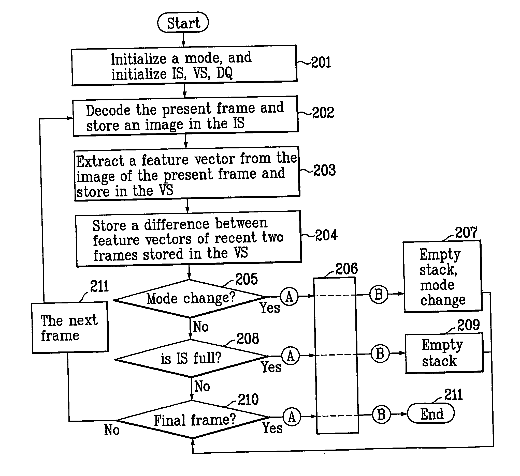
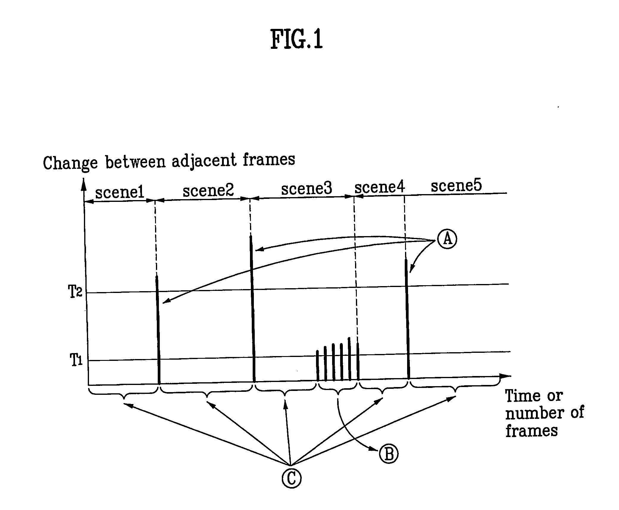
[0030] Reference will now be made in detail to the preferred embodiments of the present invention, examples of which are illustrated in the accompanying drawings. In describing the embodiments, same parts will be given the same names and reference symbols, and additional description of which will be omitted. FIG. 1 illustrates a diagram showing an image difference between adjacent frames along a time axis.

[0031] Referring to FIG. 1, scenes each having a plurality of frames arranged along a time axis, with the frame in each scene having image feature vectors calculated based on image features, such as colors, and edge intensities, and changes between adjacent frames calculated by using the image feature vectors are illustrated.

[0032] The frames in each scene can be sorted as frames with changes between adjacent frames, and frames without changes between adjacent frames, with reference to a difference of image feature vectors. With reference to threshold values T1 and T2 (T12) in th...


PUM


Abstract

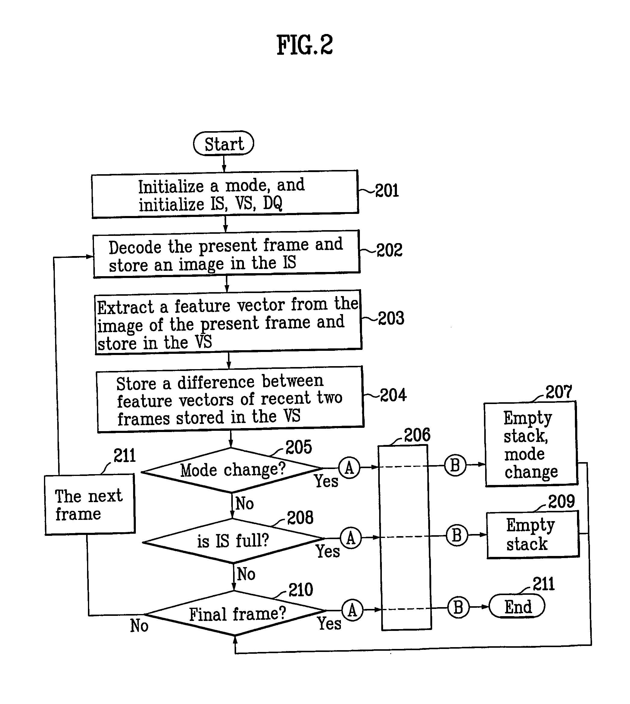
A scene change detector algorithm in image sequence is disclosed, in which a two-stage detecting process is applied to perceive a scene change in a precise and safe way. The algorithm includes classifying images into two different states, a transition state and a stationary state, after determining whether there is any change in adjacent frames, and confirming the scene change by rechecking whether there is the scene change in the classified frames.

Description

TECHNICAL FIELD [0001] The present invention relates to a method for detecting a scene change from digital images, and more particularly, to a method for detecting a scene change from digital images by using two stage detection process, and a method of extracting a key frame. BACKGROUND ART [0002] Recently, starting from video search by means of video indexing, a variety of multimedia service systems have been developed. In general, since the digital video has an enormous data quantity, and similar images continuous within one scene, the video can be searched effectively by indexing the video in scenes. In this instance, a technology for detecting a scene change time point, and extracting a key frame, a representative image of the scene, is essential in constructing a video indexing and searching system. [0003] Objects of the method for detecting a scene change lie on detection of the following scene changes. [0004] ① Cut: a sudden image change. [0005] ② Fade: an image change while ...

Claims


Application Information

Patent Timeline
IPC IPC(8): G06K9/46G06T1/00G06T7/00H04N5/14
CPCH04N5/147
Inventor KIM, YONG SUNG
Owner KONAN TECHNOLOGY
Learn More