
Time division multiplexing radio system for controlling transmission power

a radio system and transmission power technology, applied in the field of time division multiplexing radio systems, can solve the problems of increasing the power increasing the level of leaked power, and increasing the leaked power to vary, so as to accurately detect the power that leaked into adjacent channels, improve transmission characteristics, and improve the effect of accuracy

Inactive Publication Date: 2009-02-24
PANASONIC CORP
View PDF9 Cites 9 Cited by
  • Summary
  • Abstract
  • Description
  • Claims
  • Application Information

AI Technical Summary

Benefits of technology

[0010]A second object of the present invention is to accurately detect power that leaks into an adjacent channel, so that information about the detected leakage power can be used for control of transmission power.
[0011]A third object of the present invention is to, in a precise and stable manner, detect an adjacent-channel leakage power ratio, such that transmission power can be controlled with precision and stability, thus being able to provide a time-division multiplexing radio system with improved transmission characteristics.
[0012]A fourth object of the present invention is to make it possible that precisely detected and steady information about the above adjacent channel leakage power ratio is used for a transmission check of transmission carried out before actual transmission.
[0013]In order to realize the first object, according to one example of the present invention, there is provided a time-division multiplexing radio system equipped with a transmitter and a receiver, comprising: a directional coupler arranged at an output side of an amplifier of the transmitter and of which outputs are coupled with a side to an antenna and a side to the receiver; a reception RF switch arranged at an input side of a Frequency converter of the receiver and of which inputs are coupled with a side to the antenna and a side to the directional coupler; setting means for setting the receiver so that the receiver receives an adjacent channel under transmission; switchover means for switching over the reception RF switch to the side to the directional coupler under the transmission; and leakage power detecting means for detecting an adjacent-channel leakage power under the transmission Accordingly, the receiver for the present channel is utilized to detect adjacent-channel leakage power with higher precision and stability, without possessing a second detection circuit dedicated to the adjacent-channel leakage power.
[0014]In order to realize the second object, according to a second embodiment of the present invention, there is provided a time-division multiplexing radio system equipped with a transmitter and a receiver, comprising: a directional coupler arranged at an output side of an amplifier of the transmitter and of which outputs are coupled with a side to an antenna and a side to the receiver; a reception RF switch arranged at an input side of a frequency converter of the receiver and of which inputs are coupled with a side to the antenna and a side to the directional coupler; setting means for setting the receiver so that the receiver receives a present channel under transmission; switchover means for switching over the reception RF switch to the side to the directional coupler under the transmission; and transmission power detecting means for detecting transmission power to a present channel under the transmission. This configuration make it possible to obtain the transmission power of the present channel with higher precision.
[0017]Therefore, under the transmission of the present channel, signals of both the present channel and an adjacent channel are received to detect amounts of both transmission power of the present channel and adjacent-channel leakage power. The transmission power from the transmitter is controlled so that an adjacent-channel leakage power ratio derived from the detected power amounts meets a specified value, thus preventing or suppressing communication interference into adjacent channels in a steady manner and improving quality of transmission characteristics.

Problems solved by technology

In general, in digital modulation radio systems that use a time-division multiplex technique, large amounts of nonlinear distortion of a signal amplified by a power amplifier incorporated in a transmitter will increase power to be leaked into adjacent channels.
The larger the leaked power, the more deteriorated the modulation precision of a transmission signal which has large influence on transmission characteristics.
However, such conventional radio systems that operate on the time-division multiplexing technique have a configuration of detecting the leakage power into an adjacent channel by sensing a slight amount of leaked power from the transmission / reception switchover circuit.
This causes a level of the leaked power to vary depending on various factors, such as irregularities in quality of circuit parts or changes in surrounding environments, even when the transmitted power is kept to the same amount.
That is, in the case of the conventional radio systems, it is almost difficult to detect the leaked power of an adjacent channel with precision.
This lack of precision in detecting the leaked power makes it impossible to control the transmission power with precision and stability, which results in a problem that the linearity of the transmitted output can not be attained satisfactorily.
Accordingly, in a system with narrow band intervals between channels, a signal to be transmitted to the present channel can not be fully prevented from being leaked, resulting in a reduced detectable dynamic range of the adjacent channel.

Method used


Image

  • Time division multiplexing radio system for controlling transmission power
  • Time division multiplexing radio system for controlling transmission power
  • Time division multiplexing radio system for controlling transmission power

Examples


Embodiment Construction

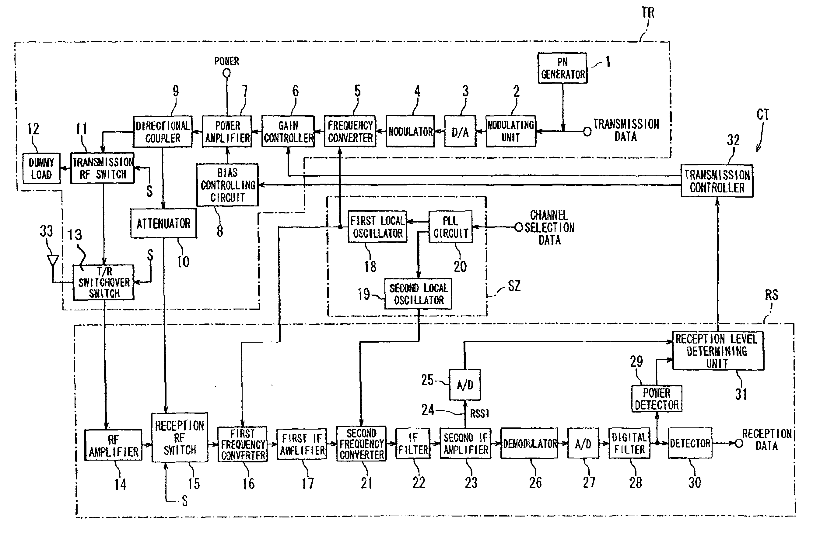
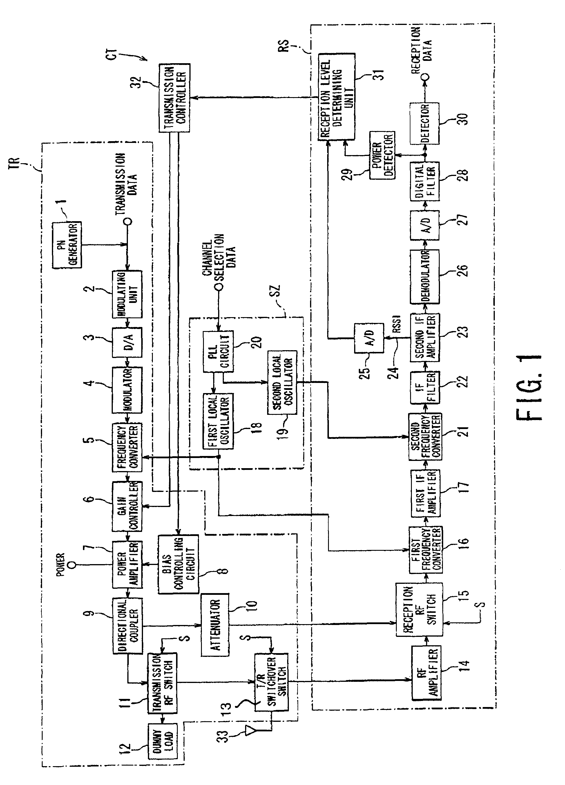
[0028]Referring to FIGS. 1 to 8, one embodiment of a time-division multiplexing radio system according to the present invention will now be explained.

[0029]FIG. 1 shows a functional block diagram of the time-division multiplexing radio system. This radio system has a function to receive power of both the present channel and an adjacent channel under transmission of the present channel so as to detect power transmitted from the present channel and power leaking into an adjacent channel. This enables detection of an adjacent-channel leakage power ratio and control of a gain of a power amplifier incorporated in a transmitter, so that the power ratio meets a specified value.

[0030]The time-division multiplexing radio system shown in FIG. 1 is equipped with a transmitter TR, receiver RS, synthesizer system SZ, and control system CT.

[0031]The transmitter TR comprises, along a path of data to be transmitted, a PN generator 1, modulator 2, D / A converter 3, modulator 4, frequency converter 5,...


PUM


Abstract

A time-division multiplexing radio system controls transmission power based on an adjacent-channel leakage power ratio with precision and stability. The system has a directional coupler arranged at an output stage of a power amplifier in a transmitter and that has outputs directed to an antenna and a receiver, and a reception RF switch arranged at an input stage of a frequency converter in a receiver and that has inputs directed to the antenna and the coupler. Under transmission, the switch is switched over to the coupler so that the receiver receives the present channel to detect transmission power thereof. Also the receiver is set to receive an adjacent channel under transmission, so that adjacent-channel leakage power is detected. Based on those pieces of detected information, the ratio is calculated. To make the power ratio meet a specified condition, the transmission power of the transmitter is controlled.

Description

BACKGROUND OF THE INVENTION[0001]1. Field of the Invention[0002]The present invention relates to a time-division multiplexing radio system, and especially to the time-division multiplexing radio system that secures the linearity of a signal output to be transmitted.[0003]2. Description of the Related Art[0004]In general, in digital modulation radio systems that use a time-division multiplex technique, large amounts of nonlinear distortion of a signal amplified by a power amplifier incorporated in a transmitter will increase power to be leaked into adjacent channels. The larger the leaked power, the more deteriorated the modulation precision of a transmission signal which has large influence on transmission characteristics. Conventionally, in order to prevent the transmission characteristics due to such nonlinear distortion from being deteriorated, there have been known techniques of detecting power leaked into an adjacent channel. The detected power is used to control the transmissi...

Claims


Application Information

Patent Timeline
Patent Type & Authority Patents(United States)
IPC IPC(8): H04B7/185H03F1/32H04B1/44H03G3/30H04B1/04H04B7/005H04B7/26H04B17/19H04B17/345H04L5/16H04W52/04H04W52/52H04W88/02
CPCH03F1/32H03G3/3047H04B1/0475H04B17/354H04W52/16H04W52/24H04B2001/0416
Inventor TOKI, KAZUYATANIGUCHI, SHOHEI
Owner PANASONIC CORP
Learn More