Flexible liner for FIBC or bag-in-box container systems with improved flex crack resistance

a flexible liner and container technology, applied in the field of flexible liners, can solve the problems of reducing the structural and/or barrier properties of the liner, affecting the flex crack resistance of the top half of the liner, and affecting the flex crack resistance of the liner

Inactive Publication Date: 2007-08-30
CDF CORP
View PDF99 Cites 39 Cited by
  • Summary
  • Abstract
  • Description
  • Claims
  • Application Information

AI Technical Summary

Benefits of technology

[0016] In one embodiment, a liner for use in a bulk container is provided. The liner comprises a first flexible portion, a second flexible portion, a first seal joining the first and second portions, a second seal joining the first and second portions, a third seal joining the first and second portions, and a fourth seal joining the first and second portions. The first portion and second portion comprises at least one ply and wherein the first portion comprises at least one more ply than the second portion.
[0017] In one embodiment, a method of flex crack protection in a flexible liner is provided. The liner comprises a first flexible portion and a second flexible portion, wherein the first portion and second portion each comprise at least one ply of flexible material. The method comprises manufacturing the first and second portion so that the first portion comprises at least one more ply than the second portion. The method also comprises sealing the plies of the first portion to the plies of the second portion.

Problems solved by technology

Alternatively, where the material of the bag is more expensive, the bag may be collapsed and returned to the shipper after the associated liner has been emptied of its contents.
Regardless of the form the liner takes, the top half of the liner is generally more susceptible to flex crack failure than the bottom half from the film moving back and forth, typically resulting from greater product movement toward the top of the product than toward the bottom.
This can lead to a breakdown of the liner's structural and / or barrier properties, possibly resulting in product degradation, loss of shelf life, contamination, damage to the contents, and / or loss of materials.
Having to add dunnage materials increases the cost and time required to ship goods and materials and does not always work, as some materials tend to settle over time, and liners are not necessarily always filled to the same height or extent.

Method used


Image

  • Flexible liner for FIBC or bag-in-box container systems with improved flex crack resistance
  • Flexible liner for FIBC or bag-in-box container systems with improved flex crack resistance
  • Flexible liner for FIBC or bag-in-box container systems with improved flex crack resistance

Examples


Embodiment Construction

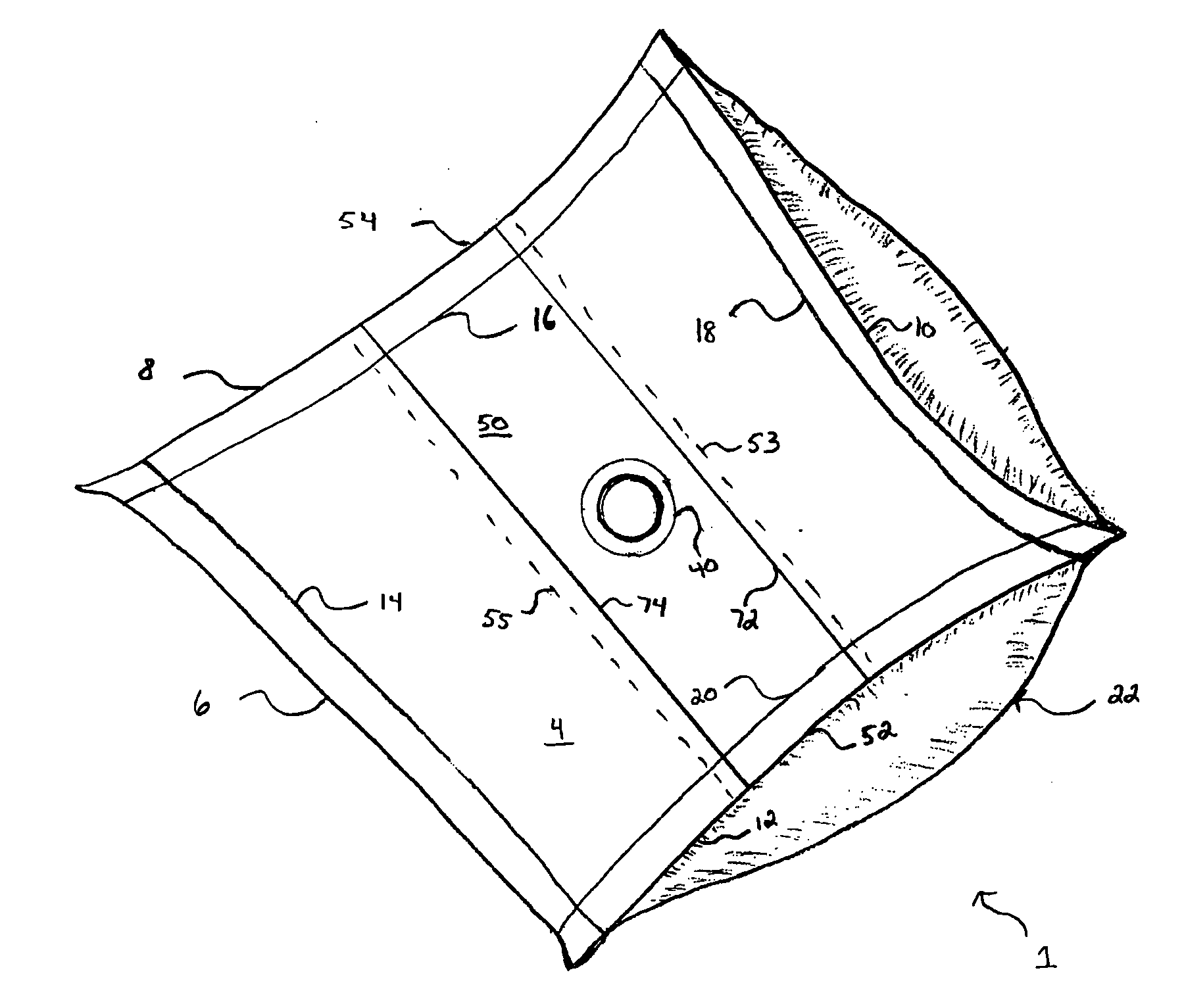
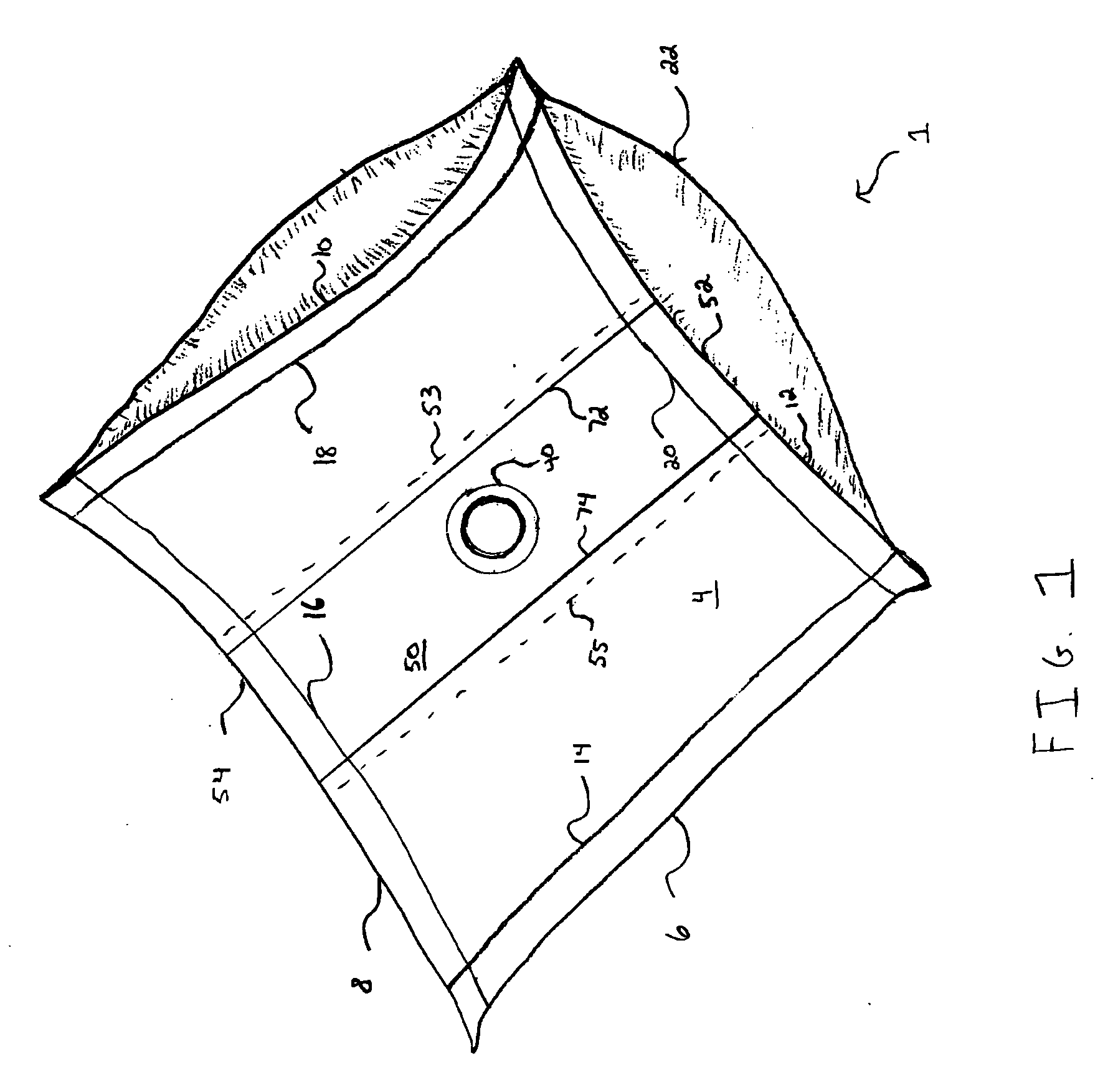
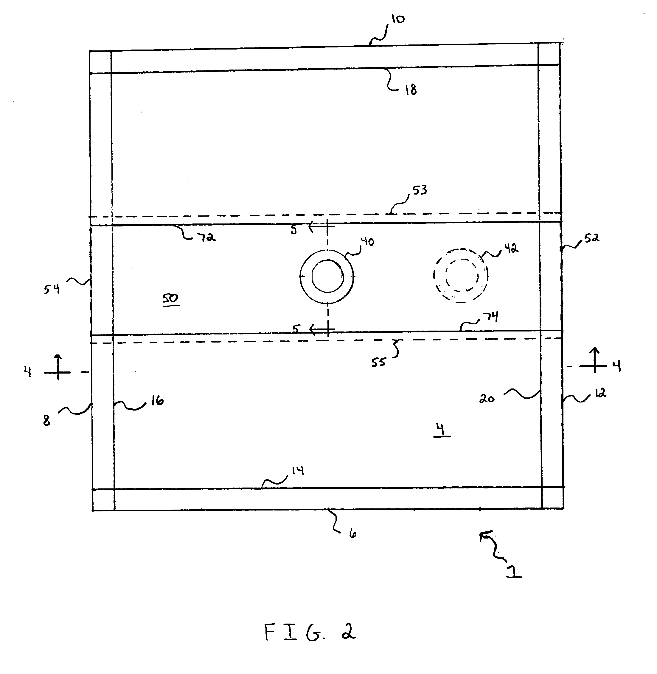
[0024] The present invention is directed to a flexible liner 1 for use in bulk containers such as those used in flexible intermediate bulk container (“FIBC”) systems or bag-in-box container systems. While certain liner embodiments are discussed herein, the particular liner configuration is generally not important to the present invention, and instead, any suitable liner configuration may be used. As will be discussed more fully below, the liner comprises a top portion and a bottom portion. The top portion and bottom portion are sealed together to form a pillow shaped liner. More specifically, longitudinal edges and lateral edges of the top portion and the bottom portion are sealed together.

[0025] In one embodiment, the top portion is composed of additional plies as compared to the bottom portion. This helps to reduce the susceptibility of the top portion to flex crack failure. This is because each ply has its own flex crack failure rate, and as the number of plies is increased, the...


PUM


Abstract

A liner for use in a bulk container is provided. The liner comprises a first flexible portion, a second flexible portion, a first seal joining the first and second portions, a second seal joining the first and second portions, a third seal joining the first and second portions, and a fourth seal joining the first and second portions. The first portion is a better barrier than the second portion.

Description

FIELD OF THE INVENTION [0001] The present invention relates to flexible liners for use in bulk containers such as those used in flexible intermediate bulk container (“FIBC”) systems or bag-in-box container systems. More particularly, the present invention relates to systems and methods for reducing flex crack failure and the need for dunnage in a FIBC or bag-in-box container system. BACKGROUND OF THE INVENTION [0002] In recent years a number of industries have adopted the FIBC or bag-in-box concept for storing and transporting liquid and particulate commodities in relatively large quantities. For example, the FIBC or bag-in-box concept has been employed for transporting in bulk such diverse products as vegetable oils, salad dressings, syrups, soy sauce, peanut butter, pharmaceuticals, talc, motor oil, industrial chemicals, detergents in liquid or powder form, and toiletry products or ingredients. [0003] The FIBC concept is a bulk container system comprising a flexible liner in a fle...

Claims


Application Information

Patent Timeline
Patent Type & Authority Applications(United States)
IPC IPC(8): B65D30/08B65D33/00B65D33/16B65D33/02
CPCB65D31/02B65D33/02Y10T156/10B65D77/062B65D88/1618B65D77/061
Inventor PLUNKETT, JAMESSULLIVAN, JOSEPH
Owner CDF CORP
Why Eureka
Try Eureka