Eureka AIR delivers breakthrough ideas for toughest innovation challenges, trusted by R&D personnel around the world.

Ferritic stainless steel welding wire and manufacturing method thereof

a technology of stainless steel and welding wire, which is applied in the direction of manufacturing tools, welding/cutting media/materials, welding apparatus, etc., can solve the problems of low toughness, low tensile strength of weld metal, weld metal breaking, etc., and achieves the effect of increasing cracking resistance and preventing wire breaking

Active Publication Date: 2006-07-27
NIPPON WELDING ROD
View PDF8 Cites 53 Cited by
  • Summary
  • Abstract
  • Description
  • Claims
  • Application Information

AI Technical Summary

Benefits of technology

[0015] An object of the present invention is to provide a ferritic stainless steel welding wire which has a small crystal grain size and can be improved in cracking resistance, flexural property, tensile strength up to high temperature, corrosion resistance and oxidation resistance.
[0016] Another object of the present invention is to provide a ferritic stainless steel welding wire of which breaking can be prevented and ease of manufacturing is attained, and a manufacturing method thereof.

Problems solved by technology

Ferritic stainless steels are low-priced compared with austenite stainless steels, and are not likely to cause heat fatigue since they has low heat expansion efficient.
As a result, the martensite crystals are coarsened, thereby weakening the weld metal.
Due to the presence of coarsened crystals, the weld metal has low tensile strength, and is also low in toughness as measured by Charpy impact test and flexural property.
Although the tensile strength can be increased by heat treatment after welding, the toughness as measured by Charpy impact test and flexural property cannot be improved even after the heat treatment.
“High corrosion resistance” means that the weld metal is not readily corroded and “low corrosion resistance” means that the weld metal is readily corroded.
The conventional ferritic stainless steel wires do not satisfy all of these requirements.

Method used


Image

  • Ferritic stainless steel welding wire and manufacturing method thereof
  • Ferritic stainless steel welding wire and manufacturing method thereof
  • Ferritic stainless steel welding wire and manufacturing method thereof

Examples


Embodiment Construction

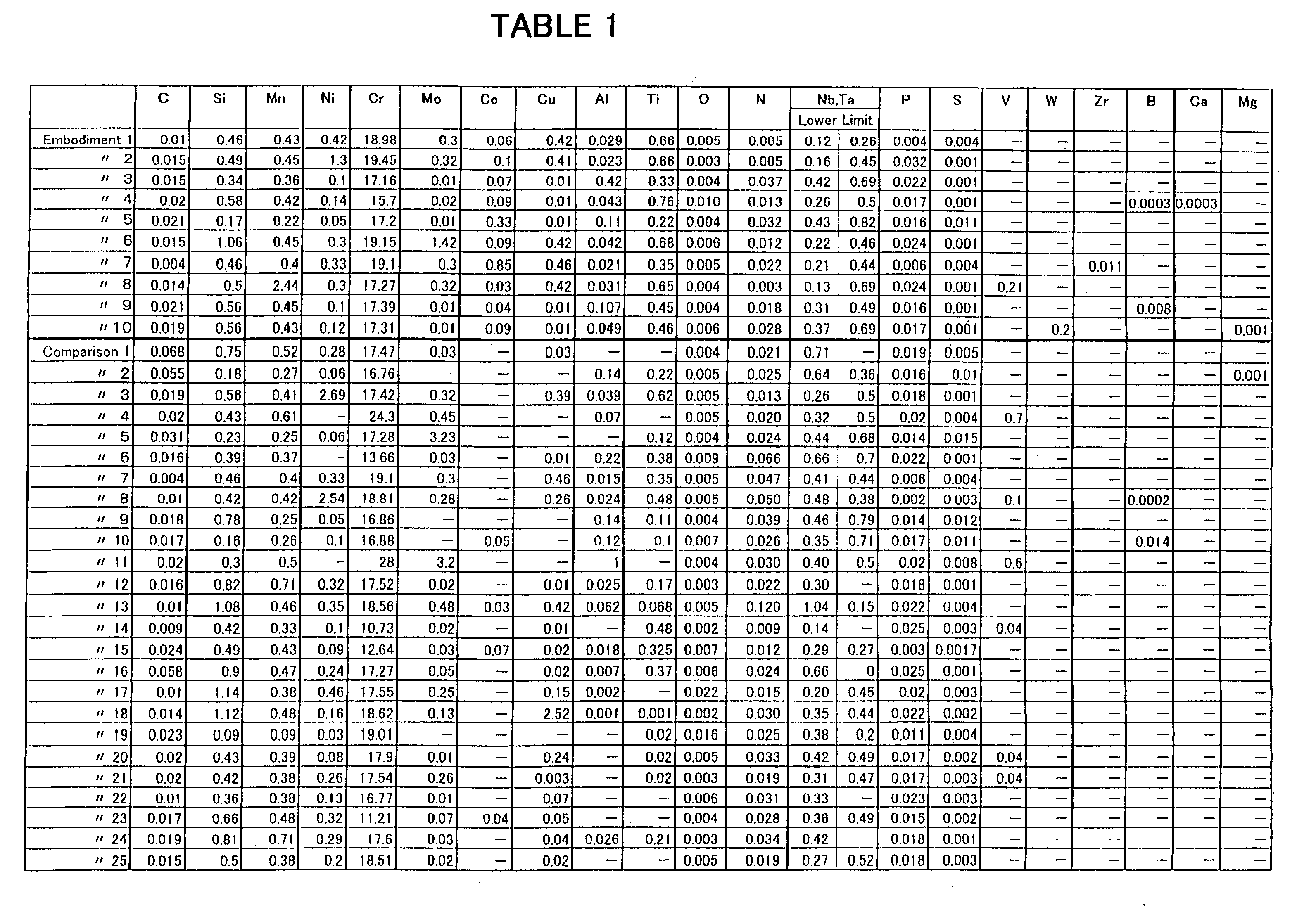
[0050] In order to confirm meritorious effects of the present invention, tests were conducted by using solid wires made of ferritic stainless steel welding wires of various compositions for the purpose of testing. First of all, several wire rods were made for the tests. They have a diameter of 5.1 to 5.5 mm, according to Embodiments 1 to 10 of the present invention and Comparisons 1 to 25 as indicated in Table 1 shown in FIG. 8. At least one of the Nb and Ta columns of the Table 1 indicates the lower limit (mass %, eight times the total mass % of C and N) for reference.

[0051] Each of the wire rods was subjected respectively to Heat Treatment 1 and Heat Treatment 2. In Heat Treatment 1, the wire rods were heated at 900 to 1100 degrees C. and then quickly cooled down. In Heat Treatment 2, the wire rods were heated at 700 to 900 degrees C. and then slowly cooled down. The grain number of each of the wire rods after the heat treatment was checked. It was also checked whether or not bre...


PUM

PropertyMeasurementUnit
Fractionaaaaaaaaaa
Fractionaaaaaaaaaa
Fractionaaaaaaaaaa

Abstract

The present invention provides a ferritic stainless steel welding wire which allows prevention of wire breaking, fine refining of crystal grains, and increased cracking resistance. A wire rod used essentially consists of, in mass %, 0.03% or less of C, 3% or less of B, 3% or less of Mn, 2% or less of Ni, 11 to 20% of Zr, 3% or less of Mo, 1% or less of Co, 2% or less of Cu, 0.02 to 2.0% of Al, 0.2 to 1.0% of Ti, 0.02% or less of O, 0.04% or less of N, at least one of Nb and Ta, the mass % thereof being eight times the total mass % of the C and N to 1.0 mass %, and the balance of Fe and unavoidable impurities. When the number of crystals per square mm (mm2) of a cross section of the wire rod is defined as m, a grain number of the crystal expressed by an exponent (G) in an expression of m=8×2G is set to 3 to 10 by the heat treatment.

Description

TECHNICAL FILED OF THE INVENTION [0001] The present invention relates to a ferritic stainless steel welding wire commonly used in gas shielded arc welding as well as a manufacturing method thereof, more specifically to a ferritic stainless steel welding wire suitable for use in welding parts for an automobile exhaust system as well as a manufacturing method thereof. BACKGROUND OF THE INVENTION [0002] A ferritic stainless steel has been known as a raw material in manufacturing a wire to be used for gas shielded arc welding. Ferritic stainless steels are low-priced compared with austenite stainless steels, and are not likely to cause heat fatigue since they has low heat expansion efficient. A weld metal formed by using such wire (a metal of a welded portion where a welded base material and a welding material or welding wire have been mixed) exhibits excellent cracking resistance in the presence of a chloride. In some cases where a ferritic stainless steel is used as a base material in...

Claims


Application Information

Patent Timeline
IPC IPC(8): B23K35/34
CPCB23K35/308B23K35/40C21D8/065C22C38/42C22C38/44C22C38/50B23K35/3086C22C38/28
Inventor KOBAYASHI, MASAAKINONAKA, SATORUAGATA, YUKIOSAITO, TEIICHIROITO, TADASHI
Owner NIPPON WELDING ROD
Why Eureka
Eureka Blog
Learn More