Steel Wire Retainer For A Sliding Block

Active Publication Date: 2007-08-30
HIWIN TECH COPR
View PDF7 Cites 17 Cited by
  • Summary
  • Abstract
  • Description
  • Claims
  • Application Information

AI Technical Summary

Benefits of technology

[0018] The primary objective of the present invention is to provide a

Problems solved by technology

Although the technology for linear transmission element is developing fast, consumers still need the technology to be improved uninterruptedly.
Therefore, there are still some problems to be solved.
However, this metal board is impractical because of the following reasons:
First, the metal board 12 is made by pressing and folding process, accordingly its production cost is relatively high.
Second, the metal board 12 is fixed on the inner surface of the sliding block 10 by screws 141, the metal board 12 must be processed to form threaded holes, and this will

Method used


Image

  • Steel Wire Retainer For A Sliding Block
  • Steel Wire Retainer For A Sliding Block
  • Steel Wire Retainer For A Sliding Block

Examples


Embodiment Construction

[0034] The foregoing, and additional objects, features and advantages of the present invention will become apparent from the following detailed description of preferred embodiments thereof, taken in conjunction with the accompanying FIGS. 4-7.

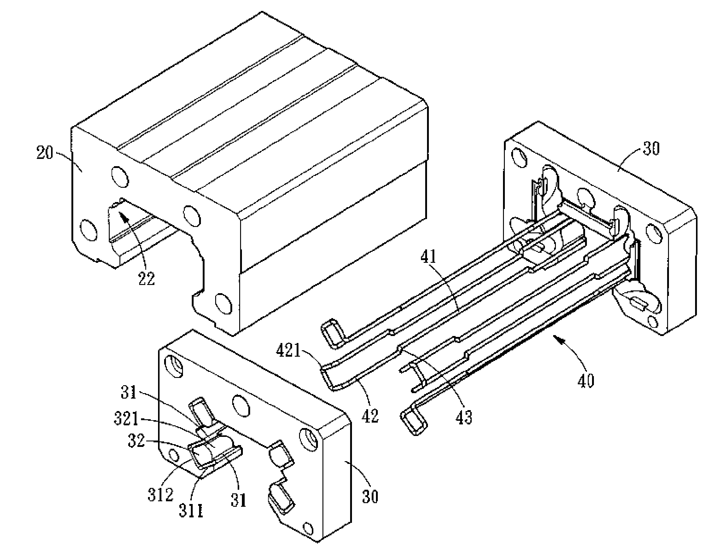
[0035] A steel wire retainer for a sliding block in accordance with the present invention comprises a sliding block 20, two end caps 30 and four steel wire retaining members 40.

[0036] The sliding block 20 is formed in its inner surface with four rolling grooves 22 along which the balls 21 roll.

[0037] The two end caps 30 are disposed at both ends of the sliding block 20, and each of the end caps 30 is defined with four locking grooves 31 to be aligned with the four rolling grooves 22 of the sliding block 20 (the two end caps 30 are oppositely arranged). In each of the locking grooves 31 is formed a locking section 311 that is vertical to the axis of the rolling grooves 22 of the sliding block 20. A pushing block 32 having an arc-shaped protru...


PUM


Abstract

A steel wire retainer for a sliding block comprises a plurality of steel wire retaining members, each of which includes a locking section on the sliding block and a plurality of steel wire retaining members. The steel wire retaining members each has a hook formed on the retaining portion thereof for hooking the locking section of the sliding block. The restraining portion of the respective steel wire retaining members will cooperate with the rolling grooves of the sliding block to form a ball rolling path, and the restraining portion of the respective steel wire retaining members is formed with a plurality of reinforced folding portions. The simple, low cost and easily assembled steel wire retaining members have sufficient support strength and are suitable for various sized sliding blocks and can make the linear transmission apparatus operate stably.

Description

BACKGROUND OF THE INVENTION [0001] 1. Field of the Invention [0002] The present invention relates to a retainer used in a sliding block of a linear guideway, and more particularly to a simple, low cost and easily assembled steel wire retainer for a sliding block, which has high quality and can meet the market's requirement. [0003] 2. Description of the Prior Art [0004] Since linear transmission products are being applied more and more widely in the modern industry, various linear transmission mechanisms have widely come into human life, manufacturing factory and high science and technology instruments, such as linear guideway, ball screw, and the like. Particularly in a large-scale precision mechanism are usually installed various large and small ball screws or linear guideway systems. Although the technology for linear transmission element is developing fast, consumers still need the technology to be improved uninterruptedly. Therefore, there are still some problems to be solved. A...

Claims


Application Information

Patent Timeline
IPC IPC(8): F16C29/06
CPCF16C29/0647F16C29/0607
Inventor TSAI, CHIUNG-HUICHEN, EN-CHIEH
Owner HIWIN TECH COPR
Why Eureka
Try Eureka