Image forming apparatus which controls heating width of fixing device

a technology of fixing device and forming apparatus, which is applied in the direction of electrographic process apparatus, instruments, optics, etc., can solve the problems of late control of heating width, relative large amount of heat applied to the fixing belt, and insufficient control of heating width

Inactive Publication Date: 2007-08-30
RICOH KK
View PDF5 Cites 24 Cited by
  • Summary
  • Abstract
  • Description
  • Claims
  • Application Information

AI Technical Summary

Benefits of technology

[0011]According to an aspect of the invention, an image forming device includes a fixing section, a sheet-width detector, a heating-width changing mechanism, a mixed feeding detector, and a controller. The fixing section includes at least a fixing member that fixes a toner image on a recording medium upon application of heat thereto. The sheet-width detector detects a width of the recording medium and outputs a sheet-width signal. The heat-width changing mechanism changes a heating width of the fixing member. The mixed feeding detector detects whether or not mixed feeding of a plurality of sheets of the recording medium having different widths is performed during a successive sheet feeding, and outputs a mixed feeding signal. The controller controls the heating-width changing mechanism to control the heating width based on the sheet-width signal and the mixed feeding signal.

Problems solved by technology

Thereby, a relatively large amount of heat is applied to the fixing belt in a short time period.
However, when the width of the recording medium is frequently switched for one printing operation, the control of the heating width is late due to the response speed of the mechanical operation or the response speed by the heat capacity of the fixing member.
Thereby, the heating width is not properly controlled.
When a related art heat fixing device with a low-speed and low-heat amount and a high-speed and high-heat amount is used, the temperature of a non-sheet feeding area cannot reach a risk range immediately because the control of the heating width is late.

Method used


Image

  • Image forming apparatus which controls heating width of fixing device
  • Image forming apparatus which controls heating width of fixing device
  • Image forming apparatus which controls heating width of fixing device

Examples


Embodiment Construction

[0023]In describing exemplary embodiments illustrated in the drawings, specific terminology is employed for the sake of clarity. However, the disclosure of this patent specification is not intended to be limited to the specific terminology so selected and it is to be understood that each specific element includes all technical equivalents that operate in a similar manner.

[0024]Referring now to the drawings, wherein like reference numerals designate identical or corresponding parts throughout the several views, an image forming apparatus 1 according to an exemplary embodiment of the present invention is described.

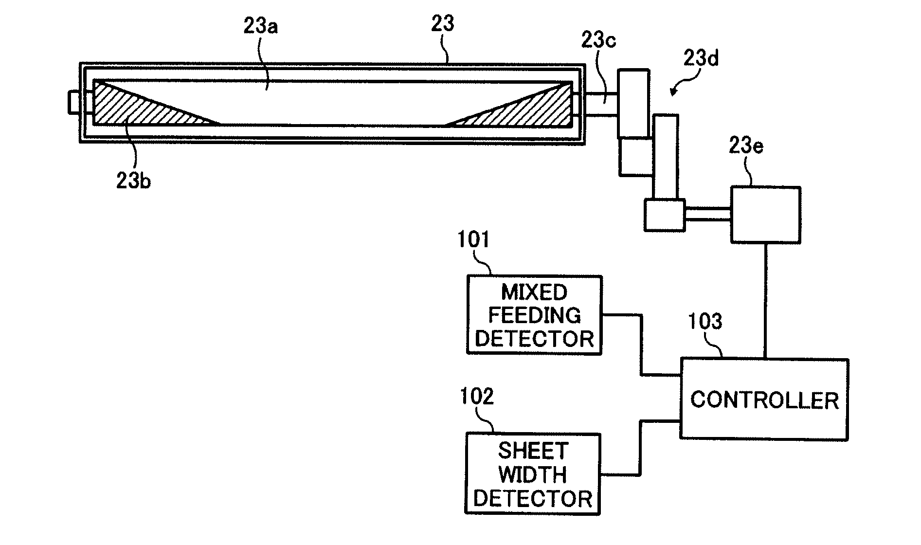
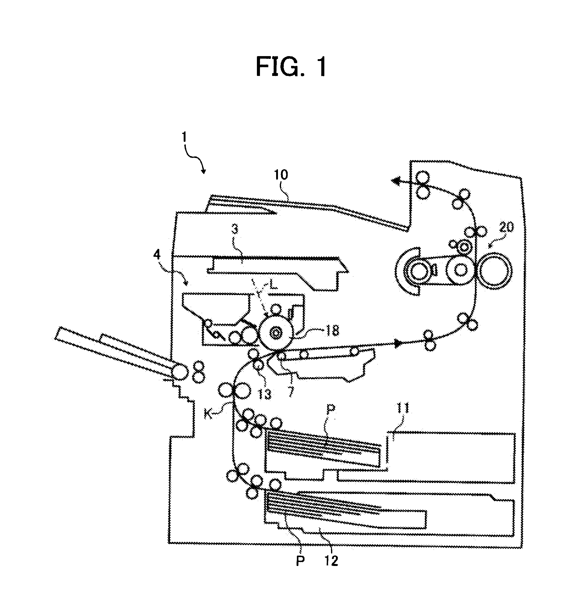
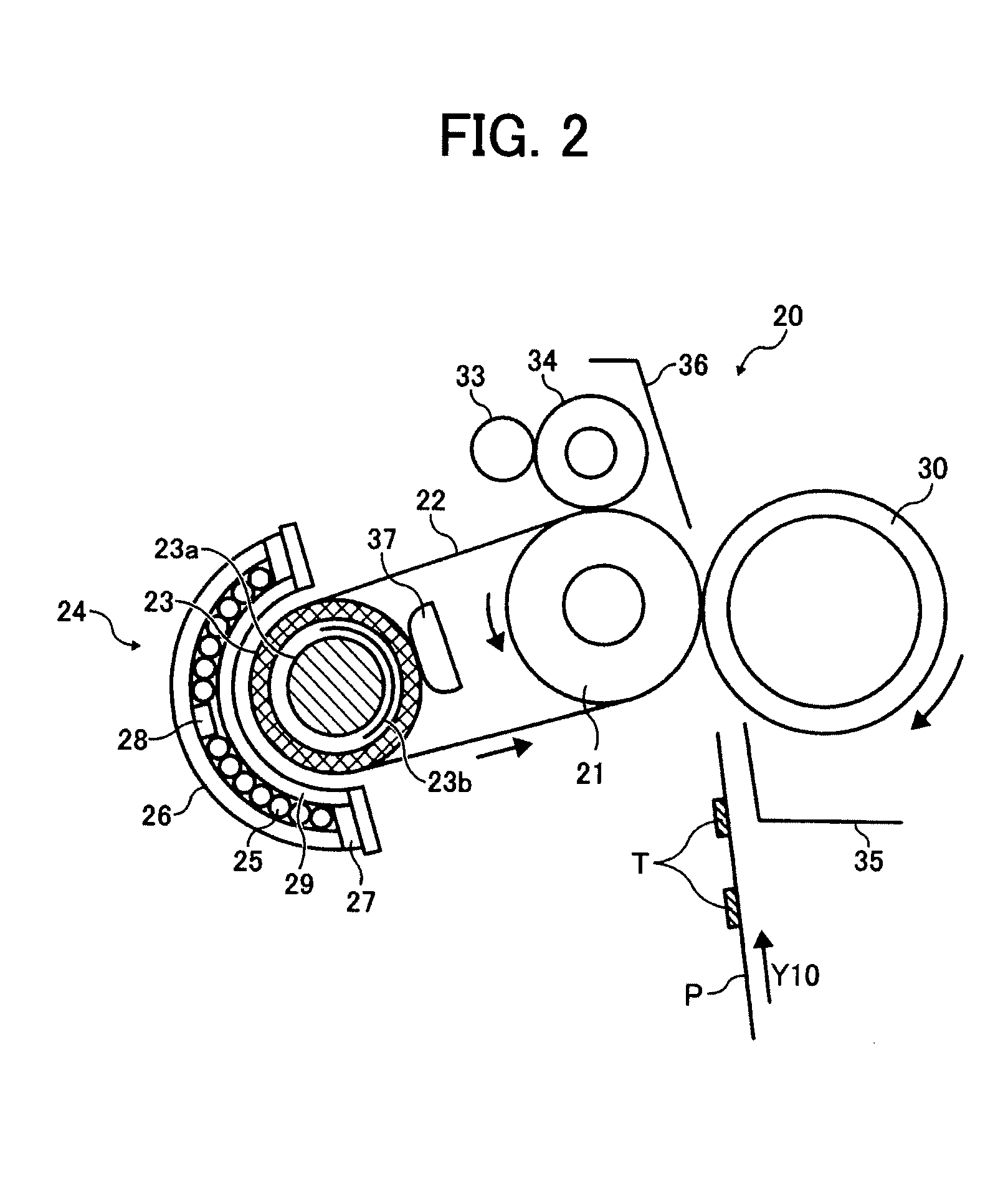
[0025]Referring to FIG. 1, the image forming apparatus 1 includes an exposure unit 3, a fixing device 20, a transfer unit 7, a pair of registration rollers 13, a plurality of sheet feeding units such as a first sheet feeding unit 11 and a second sheet feeding unit 12, an ejection tray 10, and a process cartridge 4. The process cartridge includes a photoconductor drum 18. The...


PUM


Abstract

A fixing device includes a fixing section, a sheet-width detector, a heating-width changing mechanism, a mixed feeding detector, and a controller. The fixing section includes at least a fixing member that fixes a toner image on a recording medium upon application of heat thereto. The sheet-width detector detects a width of the recording medium and outputs a sheet-width signal. The heat-width changing mechanism changes a heating width of the fixing member. The mixed feeding detector detects whether or not mixed feeding of a plurality of sheets of the recording medium having different widths is performed during a successive sheet feeding, and outputs a mixed feeding signal. The controller controls the heating-width changing mechanism to control the heating width based on the sheet-width signal and the mixed feeding signal.

Description

CROSS-REFERENCE TO RELATED APPLICATION[0001]This patent application is based on Japanese patent application, No. 2006-050212 filed on Feb. 27, 2006 in the Japan Patent Office, the entire contents of which are incorporated by reference herein.BACKGROUND OF INVENTION[0002]1. Field of the Invention[0003]Exemplary aspects of the present invention relate to an image forming apparatus, and more particularly to an image forming apparatus and the changing of the heating width of its fixing device.[0004]2. Description of the Related Art[0005]In general, image forming apparatus of recent years such as copiers, printers, facsimile machines, and multifunctional peripherals employ an electro-photographic method to form a toner image on an image carrier by a series of image forming processes such as charging, writing, developing, transferring, cleaning, and discharging. The toner image on the image carrier is transferred on a recording medium such as transfer paper and overhead projector films. T...

Claims


Application Information

Patent Timeline
Patent Type & Authority Applications(United States)
IPC IPC(8): G03G15/20
CPCG03G15/2042G03G2215/00734
Inventor UENO, SATOSHI
Owner RICOH KK
Why Eureka
Try Eureka