Continuous treatment device for high-salinity high-COD chemical hazardous waste

A chemical and hazardous waste technology, applied in the field of devices for continuous treatment of high-salt and high-COD chemical hazardous wastes, can solve the problems of equipment corrosion, large land occupation, reduced thermal efficiency, etc., and achieve the effect of complete reaction and energy saving.

Active Publication Date: 2019-06-07
NANJING UNIV +1
View PDF11 Cites 5 Cited by
  • Summary
  • Abstract
  • Description
  • Claims
  • Application Information

AI Technical Summary

Problems solved by technology

A considerable part of chemical hazardous waste has the characteristics of acute toxicity, reactivity, and corrosion, which will pose a greater threat to human health and the environment. If it is not effectively disposed of, it will have a greater impact on the human body and the environment.
(3) Great resource utilization potential
However, when incineration technology treats such hazardous wastes, there are the following problems: (1) In the state of high-temperature melting, the fouling of the rotary kiln is serious, and the thermal efficiency is significantly reduced; (

Method used


Image

  • Continuous treatment device for high-salinity high-COD chemical hazardous waste
  • Continuous treatment device for high-salinity high-COD chemical hazardous waste
  • Continuous treatment device for high-salinity high-COD chemical hazardous waste

Examples


Embodiment 1

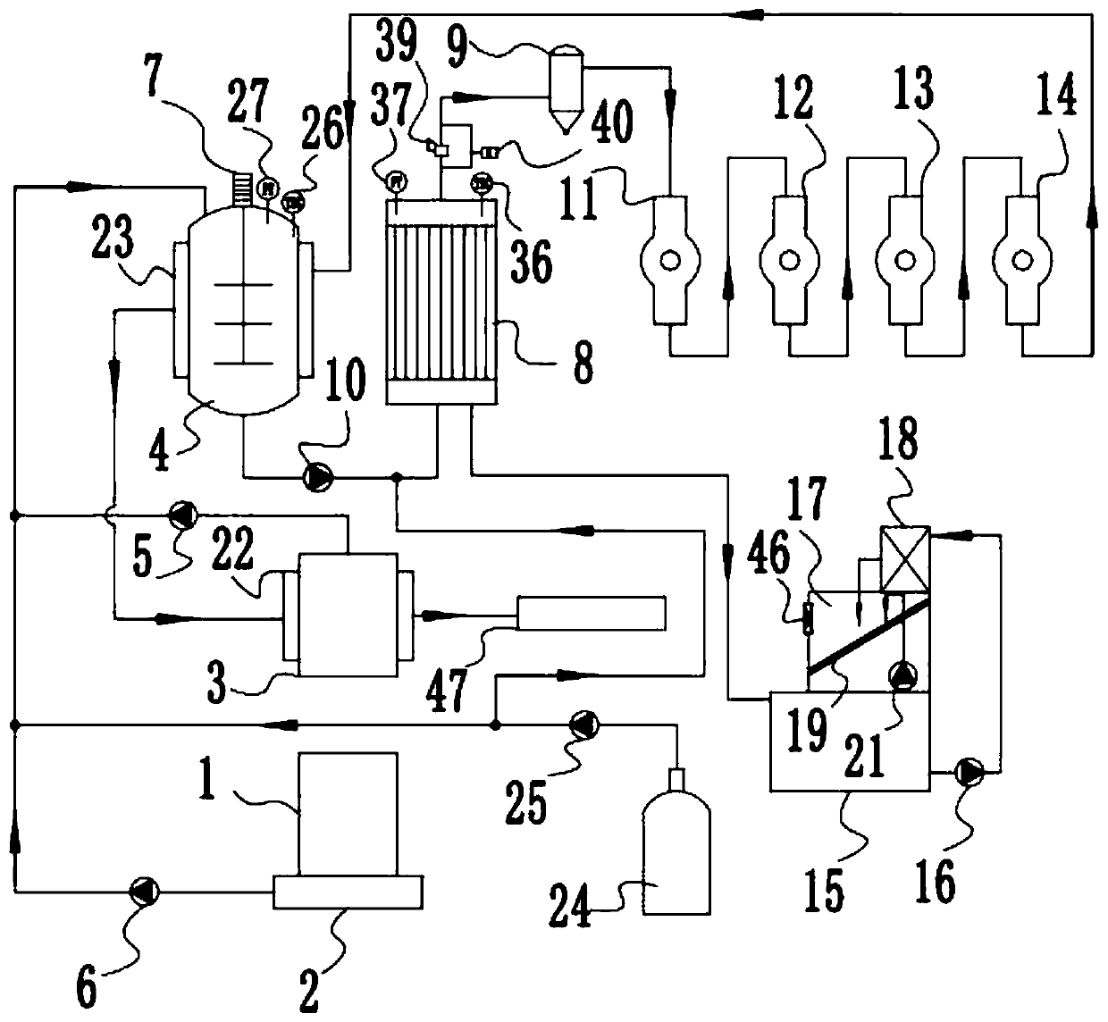
[0038] Such as figure 1 As shown, a device for continuous treatment of high-salt and high-COD chemical hazardous waste, including a pretreatment system, a hydrothermolysis system, a catalytic reforming system, a high-concentration brine evaporation and salt separation system, a heating system, an auxiliary system, and comprehensive utilization of methane systems and power supplies,

[0039] The pretreatment system includes a material storage tank 1, a metering device 2, a water tank 3, a pretreatment mixing device 4, a high-pressure water pump 5, and a material feed pump 6. The material storage tank 1 is connected to the metering device 2, and the metering device 2 is connected to the material pump 6. To the pretreatment mixing device 4, the water tank 3 is connected to the pretreatment mixing device 4 through the high pressure water pump 5, and the pretreatment mixing device 4 is provided with an agitator 7;

[0040] The hydrothermolysis system comprises a hydrothermolysis r...

Embodiment 2

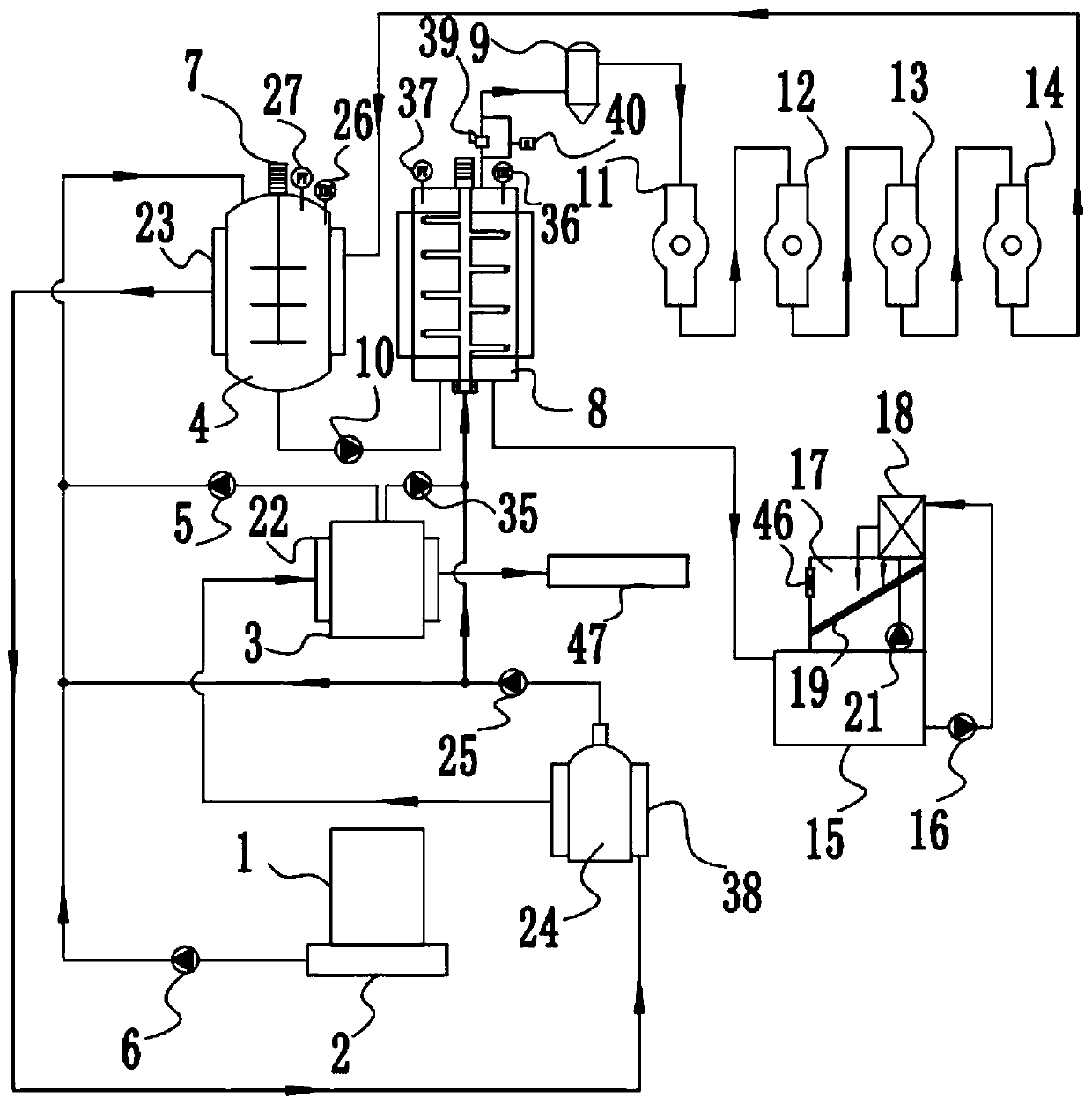
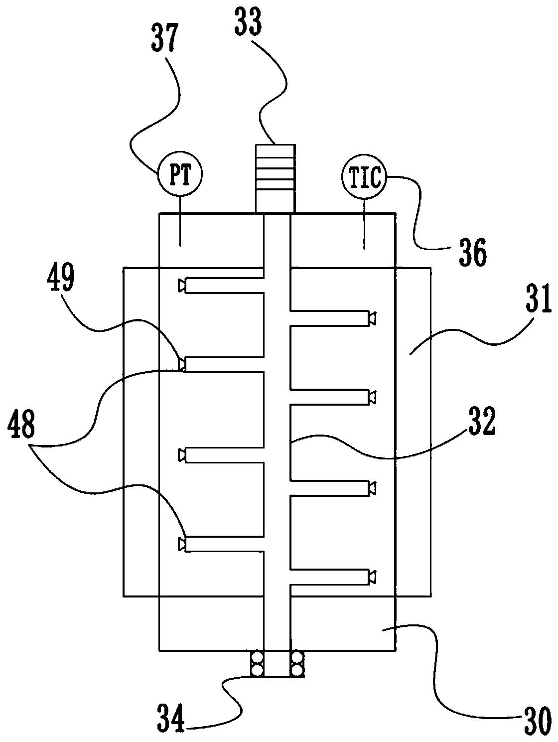
[0054] This embodiment is basically the same as Embodiment 1, the difference is:

[0055] (1) if image 3 As shown, the hydrothermolysis reactor 8 includes a reaction tank 30, a tubular heat exchange jacket 31, an aeration stirring rod 32, a stirring motor 33, and a sealed bearing 34. The tubular heat exchange jacket 31 is arranged on the reaction tank 30 outside, the stirring motor 33 is arranged on the top of the reaction tank 30, the sealed bearing 34 is arranged on the bottom of the reaction tank 30, the interior of the aeration stirring rod 32 is hollow, and the aeration stirring rod 32 is horizontally provided with 8 stirring bars 48, stirring The far end of the crossbar 48 is provided with an aeration nozzle 49, the upper end of the aeration stirring rod 32 runs through the top of the reaction tank 30 and is connected with the stirring motor 33, and the lower end of the aeration stirring rod 32 runs through the bottom of the reaction tank 30 and is connected with the up...


PUM


Abstract

The invention discloses a continuous treatment device for high-salinity high-COD chemical hazardous waste. The continuous treatment device for the high-salinity high-COD chemical hazardous waste comprises a pretreatment system, a water pyrolysis system, a catalytic reforming system, a high-concentration brine evaporation salt decomposition system, a heating system, an auxiliary system, a methane comprehensive utilization system and power source equipment. The pretreatment system comprises a material storage tank, a metering device, a water tank, a pretreatment mixing device, a high-pressure water pump and a material feeding pump. The water pyrolysis system comprises a water pyrolysis reactor, a gas-solid separator and a mixed feeding pump. The catalytic reforming system comprises a first-grade reactor, a second-grade reactor, a third-grade reactor and a fourth-grade reactor which are sequentially connected in series. The high-concentration brine evaporation salt decomposition system comprises a brine tank, a brine pump, an evaporation chamber and a heat exchanger. The heating system comprises a first heating jacket and a second heating jacket. The auxiliary system comprises an inert gas storage tank and an inert gas pump. The methane comprehensive utilization system comprises a methane recycling device which is sequentially connected with the first heating jacket, the second heating jacket and the fourth-grade reactor in series.

Description

technical field [0001] The invention belongs to the technical field of chemical hazardous waste treatment, and in particular relates to a device for continuously treating high-salt and high-COD chemical hazardous waste. Background technique [0002] Hazardous chemical waste refers to solid, semi-solid or slurry waste produced in the chemical production process, including unqualified products or intermediate products, by-products, spent catalysts, waste catalysts, etc. Waste additives, unreacted raw materials and raw material impurities, etc., also include wastes discharged directly from reaction devices or wastes discharged from corresponding devices during product hanging, separation, and washing, as well as dust discharged from air pollution control facilities, and waste generated during wastewater treatment Sludge, solid waste generated from equipment maintenance and accident leakage, etc. [0003] Hazardous chemical waste has the following characteristics: (1) The produ...

Claims


Application Information

Patent Timeline
IPC IPC(8): B09B3/00C02F11/00C02F11/10C02F1/04C07C9/04C07C1/02C02F101/30
CPCY02W10/40Y02W30/20
Inventor 吕路王林平黄前霖徐敬生张炜铭潘丙才
Owner NANJING UNIV
Why Eureka
Try Eureka