Methods and devices for delivery of prosthetic heart valves and other prosthetics

Inactive Publication Date: 2007-08-30
AORTX
View PDF99 Cites 680 Cited by
  • Summary
  • Abstract
  • Description
  • Claims
  • Application Information

AI Technical Summary

Benefits of technology

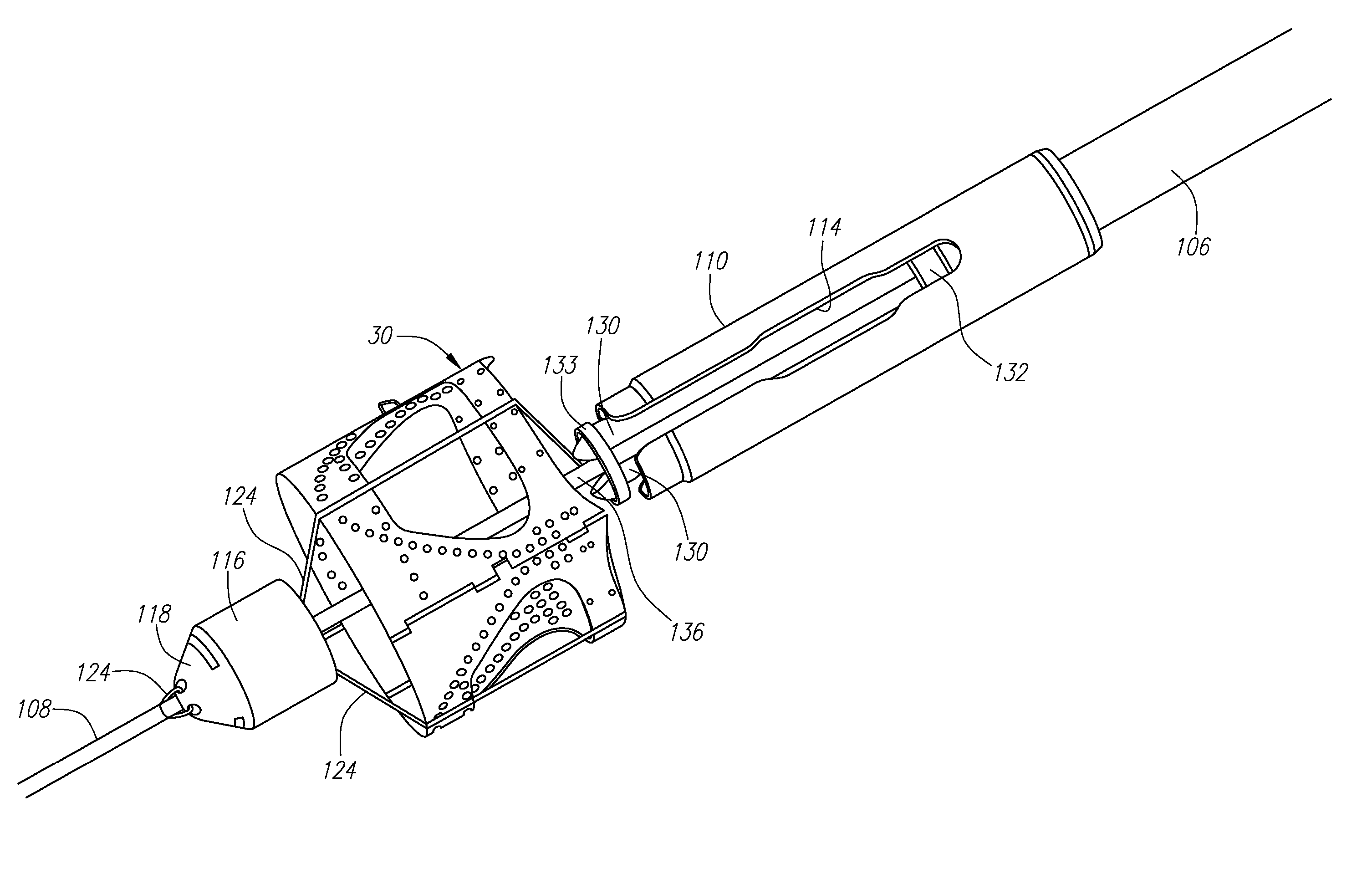
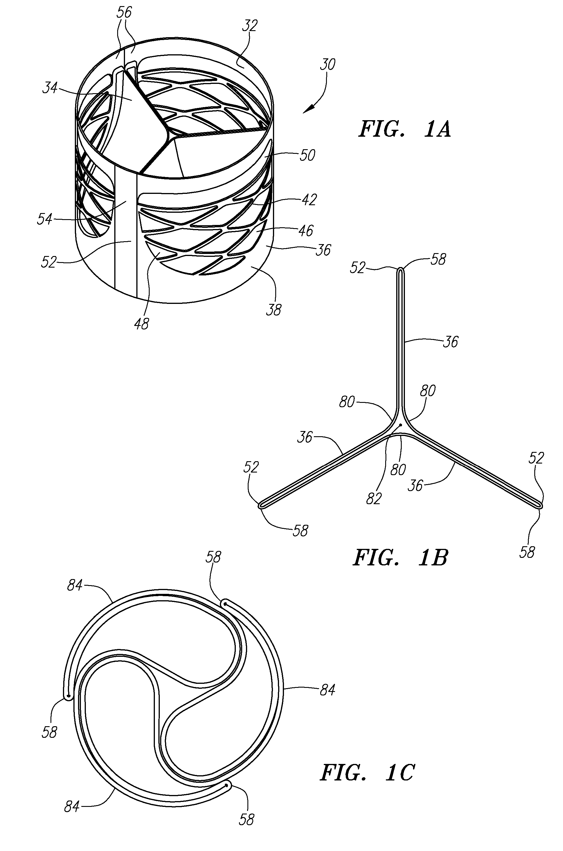
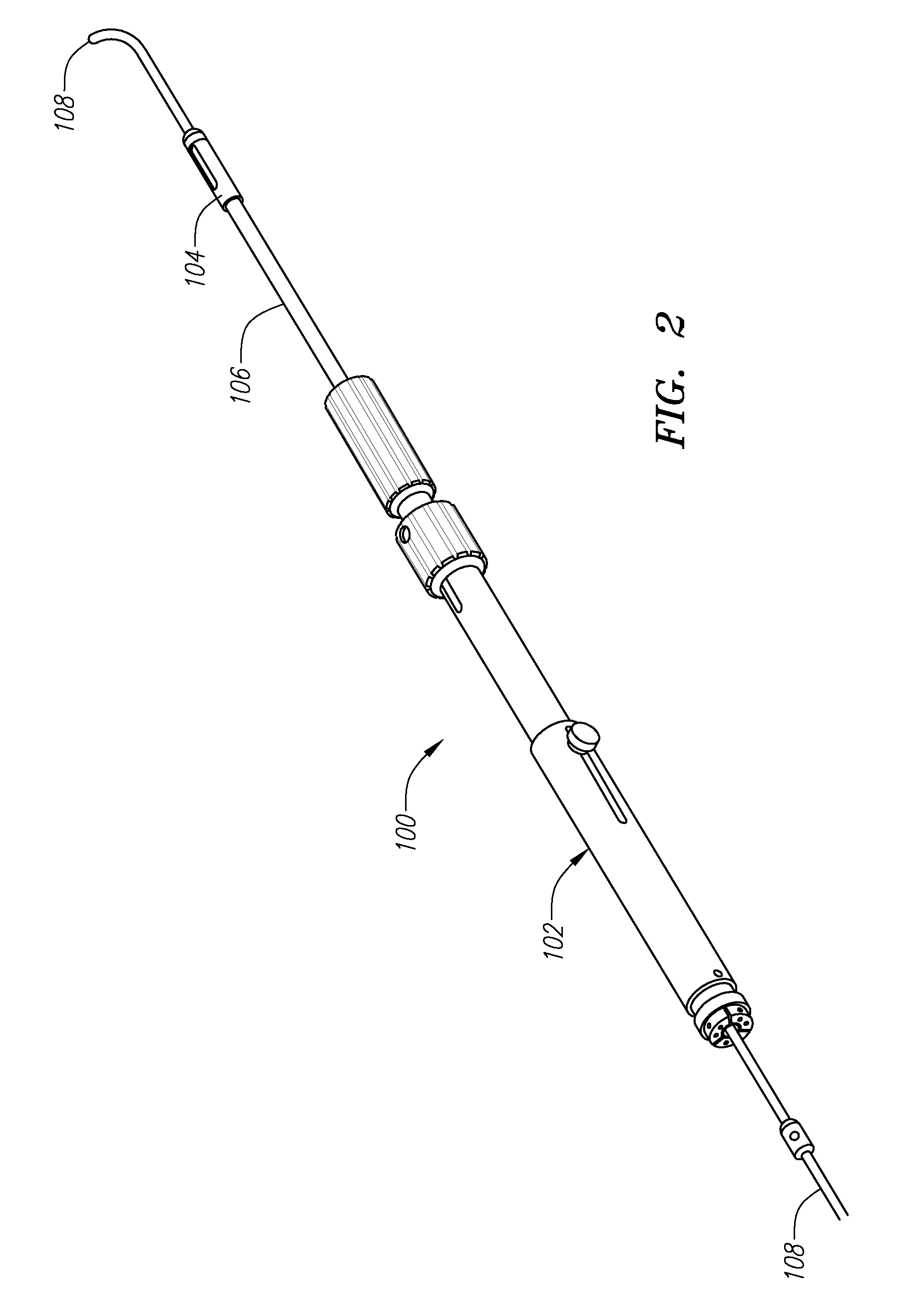
[0023] In a second aspect of the present invention, several optional active deployment mechanisms are described. The active deployment mechanisms are intended to convert a prosthetic valve, scaffolding structure, or similar device from an undeployed, partially deployed, or not-fully deployed state to its fully expanded state. Several of the active deployment mechanisms take advantage of the fact that the preferred prosthetic valves and scaffolding structures require only a small amount of force applied any any of a large number of points or locations on

Problems solved by technology

Incompetence refers to valves that cause inefficient blood circulation by permitting backflow of blood in the heart.
The main problem with all mechanical valves is the increased risk of blood clotting.
Such open heart surgery is particularly invasive and involves a lengthy and difficult recovery period.
Although this type of design can provide for crimpability, it provides little radial stiffness.
The recoil is due in part because of the stiffness mismatches between the device and the anatomical environment in which it is placed.
These devices also commonly cause crushing, tearing, or other deformation to the valve leaflets during the contraction and expansion procedures.
This type of design provides high radial stiffness, yet crimping results in large material strains that can cause stress fractures and extremely large amounts of stored energy in the constrained state.
High stress states during crimping can reduce the fatigue life of the device.
These devices suffer from some of the same deficiencies as those described above.

Method used


Image

  • Methods and devices for delivery of prosthetic heart valves and other prosthetics
  • Methods and devices for delivery of prosthetic heart valves and other prosthetics
  • Methods and devices for delivery of prosthetic heart valves and other prosthetics

Examples


first embodiment

[0126]FIG. 26A illustrates a first embodiment in which a balloon 220 is provided internally of a prosthetic valve 30. The balloon 220 includes a pair of broad portions 222a that correspond with the proximal and distal ends of the valve 30, and a narrowed waist portion 222b that corresponds with the middle portion of the valve 30. The balloon 220 may optionally be provided in a fixed relationship with the valve body, as illustrated in FIG. 26B, wherein the balloon 220 is packaged with the valve 30 as the valve 30 is loaded into the delivery catheter and delivered to a treatment location. Thus, if the valve 30 is found not to have fully expanded after deployment, the balloon 220 may be inflated to cause full deployment.

[0127] A number of optional balloon shapes and sizes are illustrated in FIGS. 26C-E. For example, in FIG. 26C, a single balloon 220 is shown having two large diameter portions 222a and a narrow, or smaller diameter portion 222b connecting the other two portions. In FIG....

embodiment 242

[0130] FIGS. 29A-B illustrate yet another deployment mechanism 242 that includes a wedge-shaped member having an upper guide 244 and a lower separator 246. As with the previous deployment mechanism 234, the present embodiment 242 be included on the distal end of a shaft that may be included with, or separate from, the delivery catheter 100. The wedge mechanism 242 is intended to be guided onto each of the hinges 52 of the undeployed or not-fully deployed valve 30. Because of the relative size and shape of the separator 246 portion of the wedge, the separator 246 causes the hinges 52 to open, thereby causing the valve panels 36 to expand to the fully deployed state.

[0131] Turning next to FIG. 30, another deployment mechanism 250 includes a torsion spring 252 mounted to the internal surface of the valve 30. The torsion spring 252 may be integrated into and / or may form part of the hinge 52 of the valve 30, but is provided with a pair of arms 254 that extend into the interior of the val...


PUM


Abstract

Prosthetic valves and their component parts are described, as are prosthetic valve delivery devices and methods for their use. The prosthetic valves are particularly adapted for use in percutaneous aortic valve replacement procedures. The delivery devices are particularly adapted for use in minimally invasive surgical procedures. The preferred delivery device includes a catheter having a deployment mechanism attached to its distal end, and a handle mechanism attached to its proximal end. A plurality of tethers are provided to selectively restrain the valve during deployment. A number of mechanisms for active deployment of partially expanded prosthetic valves are also described.

Description

CROSS REFERENCES TO RELATED APPLICATIONS [0001] This application relates to U.S. patent application Ser. No. 11 / 066,126, entitled “Prosthetic Heart Valves, Scaffolding Structures, and Methods for Implantation of Same,” filed Feb. 25, 2005, which application is hereby incorporated by reference in its entirety. The foregoing application claims the benefit of U.S. Provisional Application Ser. No. 60 / 548,731, entitled “Foldable Stent for Minimally Invasive Surgery,” filed Feb. 27, 2004, and U.S. Provisional Application Ser. No. 60 / 559,199, entitled “Method and Multiple Balloon for Percutaneous Aortic Valve Implantation,” filed Apr. 1, 2004, each of which applications is hereby incorporated by reference in its entirety.FIELD OF THE INVENTION [0002] The present invention relates generally to medical devices and methods. More particularly, the present invention relates to methods and devices for delivering and deploying prosthetic heart valves and similar structures using minimally invasiv...

Claims


Application Information

Patent Timeline
IPC IPC(8): A61F2/24
CPCA61F2/2412A61F2002/9522A61F2/2439A61F2/243A61F2/9522
Inventor FORSTER, DAVID C.HENEVELD, SCOTTWALSH, BRANDONBECKEY, BRIAN
Owner AORTX
Why Eureka
Try Eureka