Furniture-glide assembly

Inactive Publication Date: 2007-09-06
HIWATT PROD
View PDF40 Cites 30 Cited by
  • Summary
  • Abstract
  • Description
  • Claims
  • Application Information

AI Technical Summary

Benefits of technology

[0011] The invention overcomes the disadvantages in the related art in a glide assembly adapted to be securely fastened to the free end of a leg of a piece of furniture. The assembly includes a body defining a bore extending partially through the body to define an interior surface, an open end, and a closed end of the body. The free end of the leg is adapted to be inserted within the bore. A post extends from the closed end at least partially toward the open end of the body and is adapted to be received through an opening of and within the free end of the leg with the free end of the leg being adapted to be matingly received between the post and body. A clip is supported upon the post and adapted to be in abutting contact with an interior surface of the free end of the leg to securely fasten the body about the free end of the leg.
[0012] One advantage of the furniture-glide assembly of the present invention is that it can be fixedly secured to the free end of the leg of the piece of furniture such that the glide assembly can be retained to the leg when the piece of furniture is moved along a floor while maintaining sufficient contact with the floor.

Problems solved by technology

However, this type of foot suffers from many disadvantages.
The bottom surface of the conventional foot is relatively large, which increases the amount of frictional contact with the floor and causes scraping and scratching of relatively more surface area of the floor.
And, use of this type of foot generally facilitates a sliding motion across the floor and, therefore, increases the incidence of floor scraping and scratching and attendant noise.
This relatively greater amount of scraping and scratching, in turn, increases not only costs of stripping, waxing, and buffing the floor and other labor and material costs associated with maintaining the floor, but also the number of airborne particulates and, thus, pollutants in the room in which the corresponding chair or desk is used.
Furthermore, the bottom surface defines relatively more area upon which dirt, dust, sand, and other debris can gather, thus making this type of foot relatively more difficult, time-consuming, and, thus, expensive to clean and keep sanitary.
This debris can even be imbedded into the bottom surface of the foot such that the texture of the bottom surface becomes like sandpaper and, thus, scrapes and scratches the floor even more than it does otherwise.
In addition, when the chair or desk is moved along the floor, the frictional contact between this type of foot and the floor produces a perceptible often irritating noise.
In a classroom setting, especially in an elementary school where there are a substantial number of relatively young students moving or “scooting” their respective chairs and desks at any one time, this noise can be multiplied to a very significant level.
In such an especially wet environment, this type of foot—being made mostly or even entirely of metal—can rust and, hence, have a relatively shorter life, produce rust marks on the floor when the chair or desk is moved along the floor, and cause the legs of the chair or desk to be aesthetically displeasing.

Method used


Image

  • Furniture-glide assembly
  • Furniture-glide assembly
  • Furniture-glide assembly

Examples


Embodiment Construction

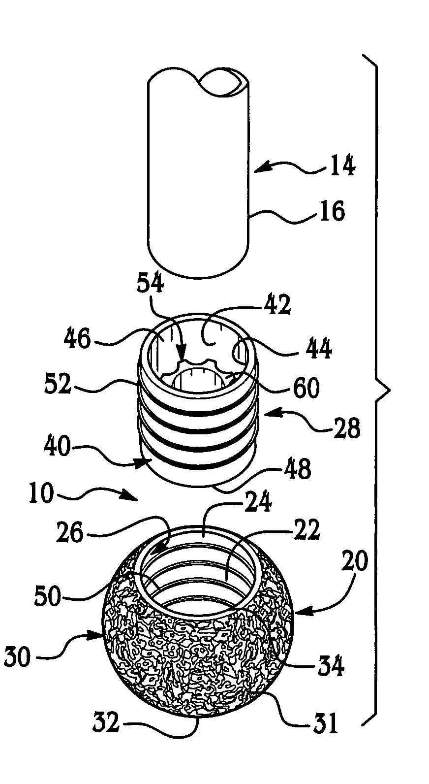
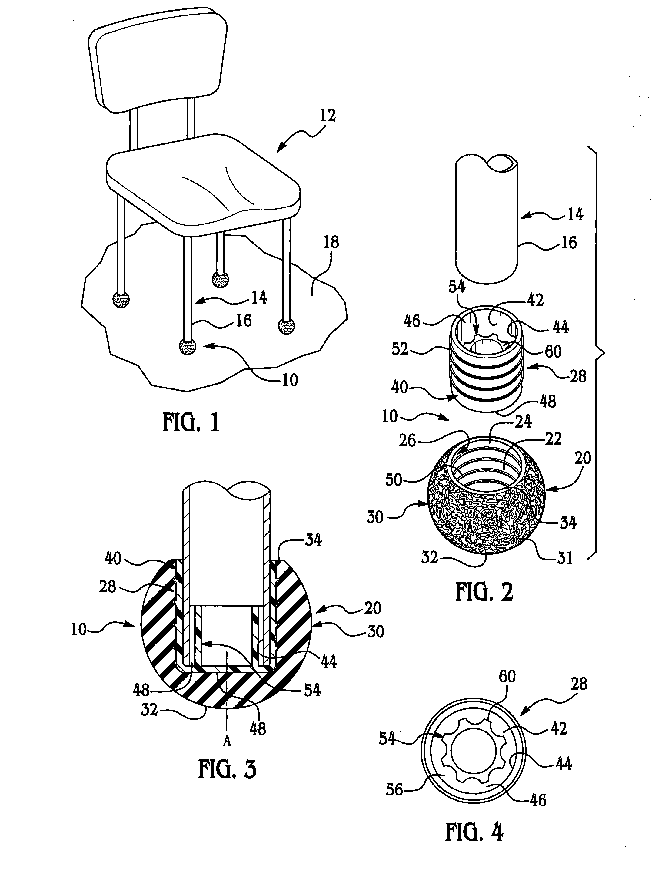
[0042] A furniture-glide assembly according to the present invention is generally indicated at 10, 110 in FIGS. 1 through 10B, where like numerals are used to designate like structure throughout the various embodiments of the glide assembly 10, 110 disclosed herein. The glide assembly 10, 110 is adapted to be removably mounted about the free end 16 of each leg, generally indicated at 14, of a piece of furniture, generally indicated at 12 in FIGS. 1 and 5. The piece of furniture 12, in general, and the legs 14, in particular, are adapted to be supported by a surface, such as a floor 18.

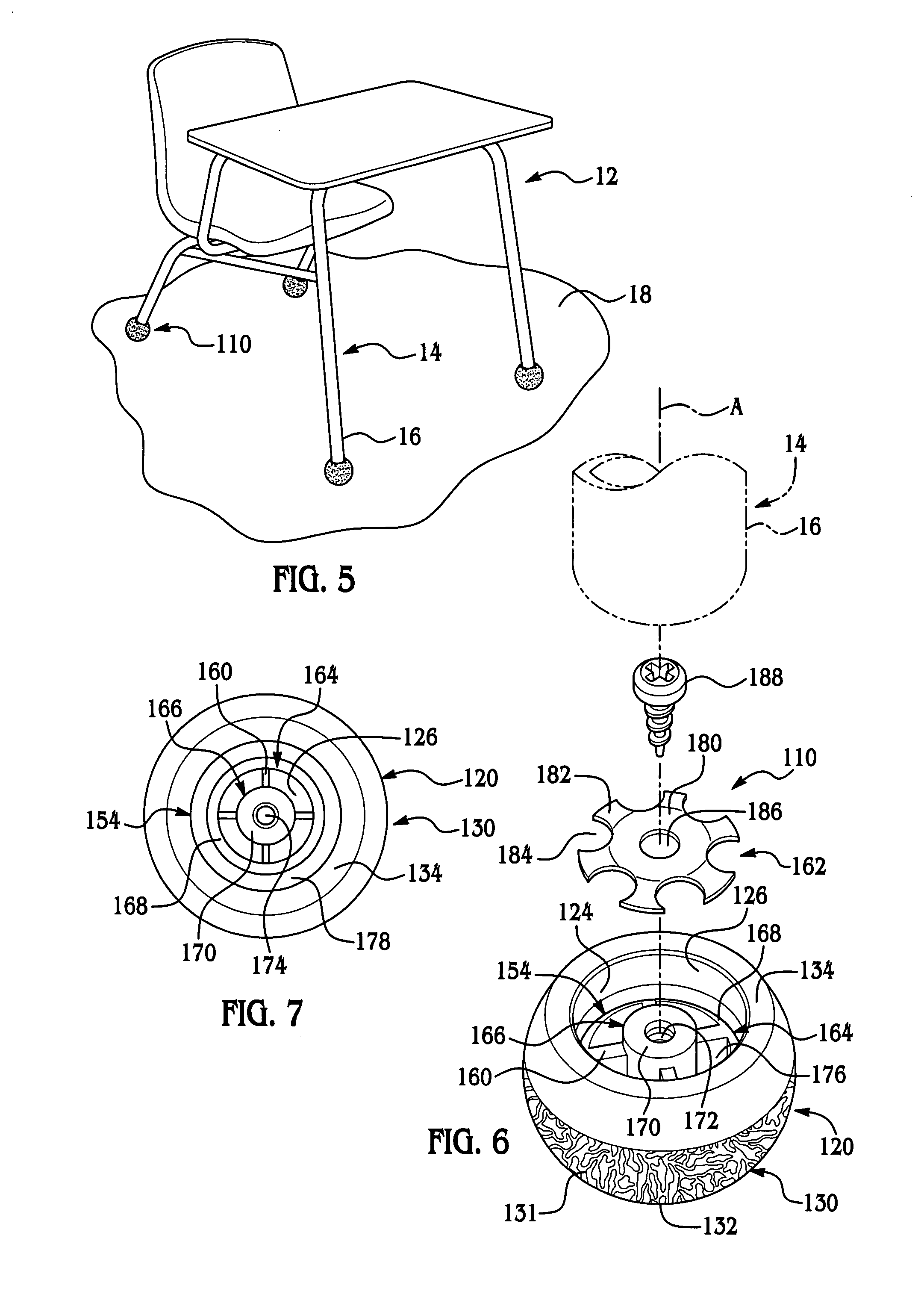
[0043] The assembly 10, 110 is described below and shown in FIG. 1 used in connection with a chair 12 and in FIG. 5 used in connection with a chair-desk combination. However, it should be appreciated by those having ordinary skill in the related art that the assembly 10, 110 can be used in connection with any suitable piece of furniture. It should also be appreciated that the assembly 10, 110 can find...


PUM


Abstract

A glide assembly is adapted to be securely fastened to the free end of a leg of a piece of furniture. The assembly includes a body defining a bore extending partially through the body to define an interior surface, an open end, and a closed end of the body. The free end of the leg is adapted to be inserted within the bore. A post extends from the closed end at least partially toward the open end of the body and is adapted to be received through an opening of and within the free end of the leg with the free end of the leg being adapted to be matingly received between the post and body. A clip is supported upon the post and adapted to be in abutting contact with an interior surface of the free end of the leg to securely fasten the body about the free end of the leg.

Description

[0001] This is a continuation-in-part application of and claims benefit to U.S. patent application Ser. No. 10 / 941,162 filed Sep. 15, 2004 and entitled “Furniture Glide Assembly.”BACKGROUND OF THE INVENTION [0002] 1. Field of the Invention [0003] The present invention relates, generally, to a glide mountable to a leg of a piece of furniture and, in particular, to a glide assembly fixedly securable about the free end of a leg of a chair or desk. [0004] 2. Description of the Related Art [0005] The free end of each leg of a piece of furniture often includes a cap, foot, glide, or the like. In many institutionalized settings, such as in a school or other educational facility, the feet disposed on the free end of the legs of a piece of furniture are designed to allow easy sliding of a chair or desk, for instance, upon a surface such as a floor. More specifically, the feet are designed to increase the amount of surface-area contact, but reduce the amount of frictional contact, between the...

Claims


Application Information

Patent Timeline
IPC IPC(8): A47B91/06
CPCA47B91/06Y10T16/209A47C7/002
Inventor CHASE, JOHN
Owner HIWATT PROD
Why Eureka
Try Eureka