Orthopedic shoe appliance and method

a technology for orthopaedic shoes and devices, applied in the field of orthopaedic corrective devices and methods, can solve the problems of large toes, large toes, and excessive mobility of the medial arch area of the foot, and achieve the effect of improving the stability of the foo

a technology for orthopaedic shoes and devices, applied in the field of orthopaedic corrective devices and methods, can solve the problems of large toes, large toes, and excessive mobility of the medial arch area of the foot, and achieve the effect of improving the stability of the foo

US20070204487A1Active Publication Date: 2007-09-06CLUFFY LLC

Image

  • Orthopedic shoe appliance and method
  • Orthopedic shoe appliance and method
  • Orthopedic shoe appliance and method

Examples


Embodiment Construction

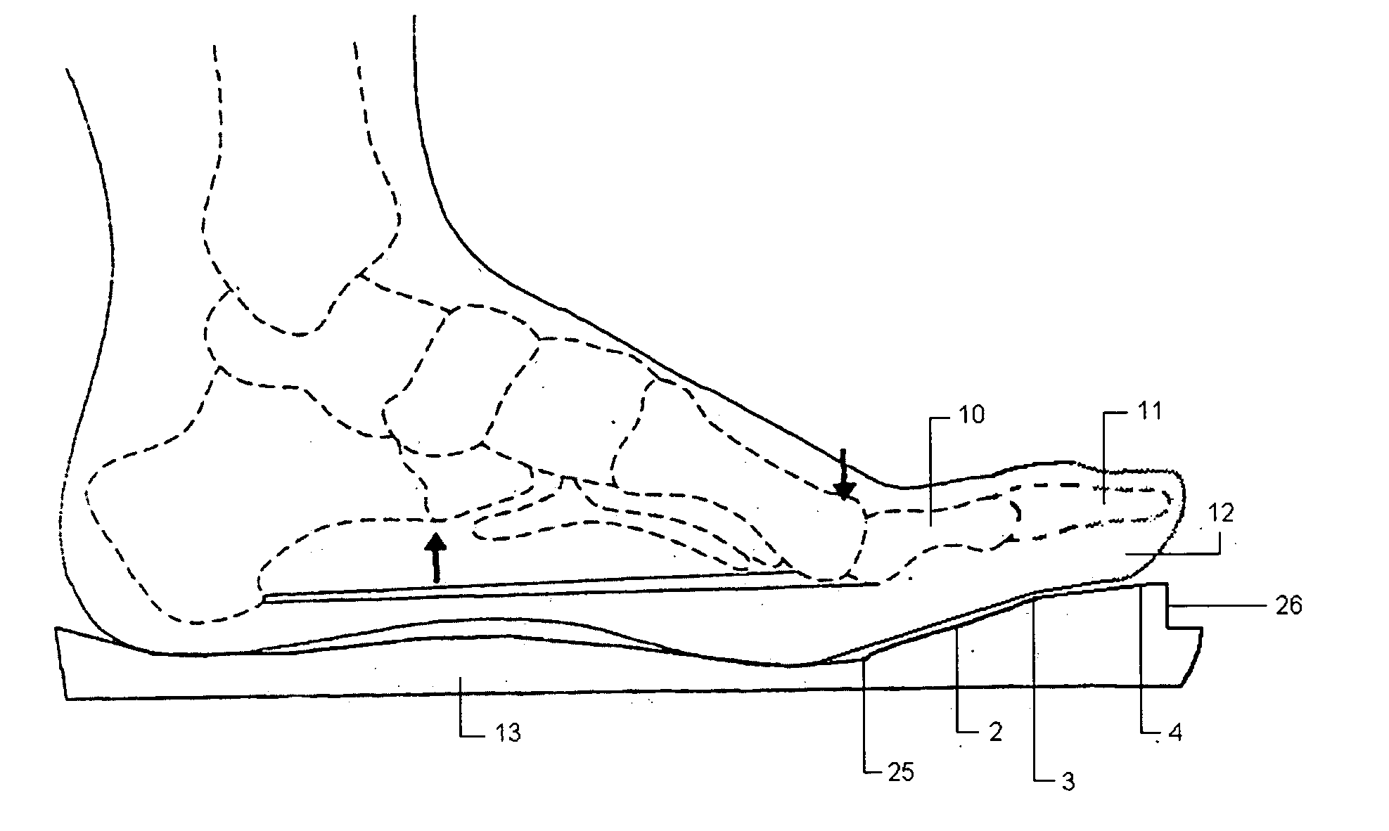
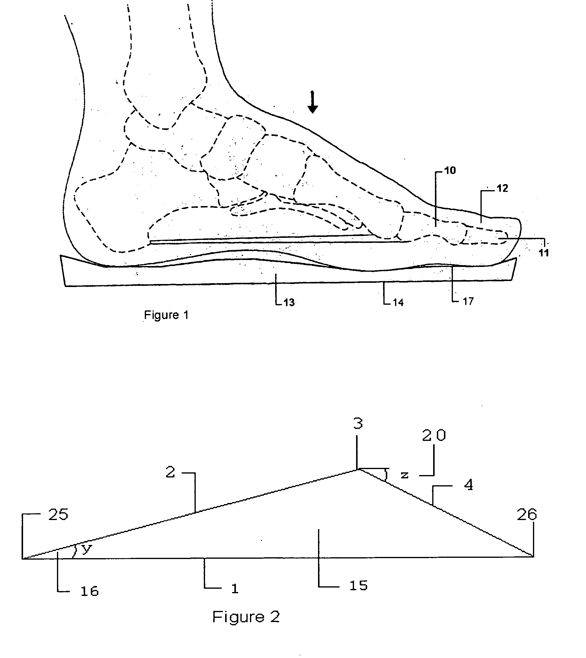
[0061] First, this invention improves the stability of the foot structure during ambulation. With increased medial column stability of the foot, pain is alleviated in the lesser metatarsal area of the foot. Elevation of the proximal phalanx accomplishes several significant biomechanical sequences which have the effect of providing a supinatory position of the subtalar and midtarsal joints as well as pronation of the longitudinal midtarsal joint. As dorsiflexion of the toes takes place in late midstance and early propulsion, the plantar fascia is placed on stretch. As this occurs, the arch height is increased or the distance between the heel and the ball of the foot is shortened. This results in overall supination of the foot structure which provides for more stability of the foot during stance.

[0062] The second advantage to the present invention is alleviation of foot pain caused by limited dorsiflexion of the first metatarsalphlangeal joint. A pronated rearfoot and a supinated for...


PUM


Abstract

An orthopedic appliance includes a slab configured to be placed underneath a big toe, forward of and not extending under a head of a first metatarsal, and wherein the slab has a predetermined height and is configured to deflect a proximal phalanx upwardly relative to the first metatarsal. A method for improving stability of a foot during ambulation includes placing an orthopedic appliance, having a predetermined height, under a big toe such that the orthopedic appliance is located forward of and does not extend under a head of a first metatarsal of the big toe; and deflecting a proximal phalanx upwardly relative to the first metatarsal.

Description

CROSS-REFERENCE TO RELATED APPLICATIONS [0001] This application is related to application Ser. No. 10 / 032,604, now U.S. Pat. No. 6,874,258, issued on Apr. 5, 2005, which is a continuation-in-part of application Ser. No. 09 / 693,235, filed on Oct. 20, 2000, now U.S. Pat. No. 6,938,363, issued on Sep. 6, 2005, which is a continuation-in-part of application Ser. No. 09 / 467,973, filed on Dec. 21, 1999, now U.S. Pat. No. 6,170,176, issued on Jan. 9, 2001.BACKGROUND OF THE INVENTION [0002] 1. Field of the Invention [0003] The invention relates generally to orthopedic corrective devices and methods. [0004] 2. Background Art [0005] When a person ambulates, or moves from place to place such as by walking, a host of triplane motions occur to the foot structure, broadly termed pronation and supination. Pronation of the foot generally involves a depression of the arch, mobility of the foot and an internal rotation of the leg. Supination generally involves an elevation of the arch and stability o...

Claims


Application Information

Patent Timeline
06 Sep 2007
Publication
US20070204487A1
IPC
A61F5/14
CPC
A61F5/14
Inventors
CLOUGH, JAMES G.