Electrical service conduit system and method of use

Inactive Publication Date: 2007-09-06
DUCTCRETE
View PDF5 Cites 2 Cited by
  • Summary
  • Abstract
  • Description
  • Claims
  • Application Information

AI Technical Summary

Benefits of technology

[0006] Accordingly, it is an object of the present invention to set forth a novel system and met

Problems solved by technology

This is clearly a very costl

Method used


Image

  • Electrical service conduit system and method of use
  • Electrical service conduit system and method of use
  • Electrical service conduit system and method of use

Examples


Embodiment Construction

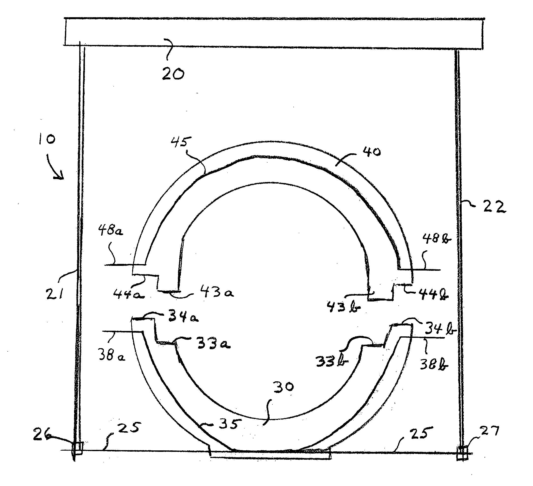
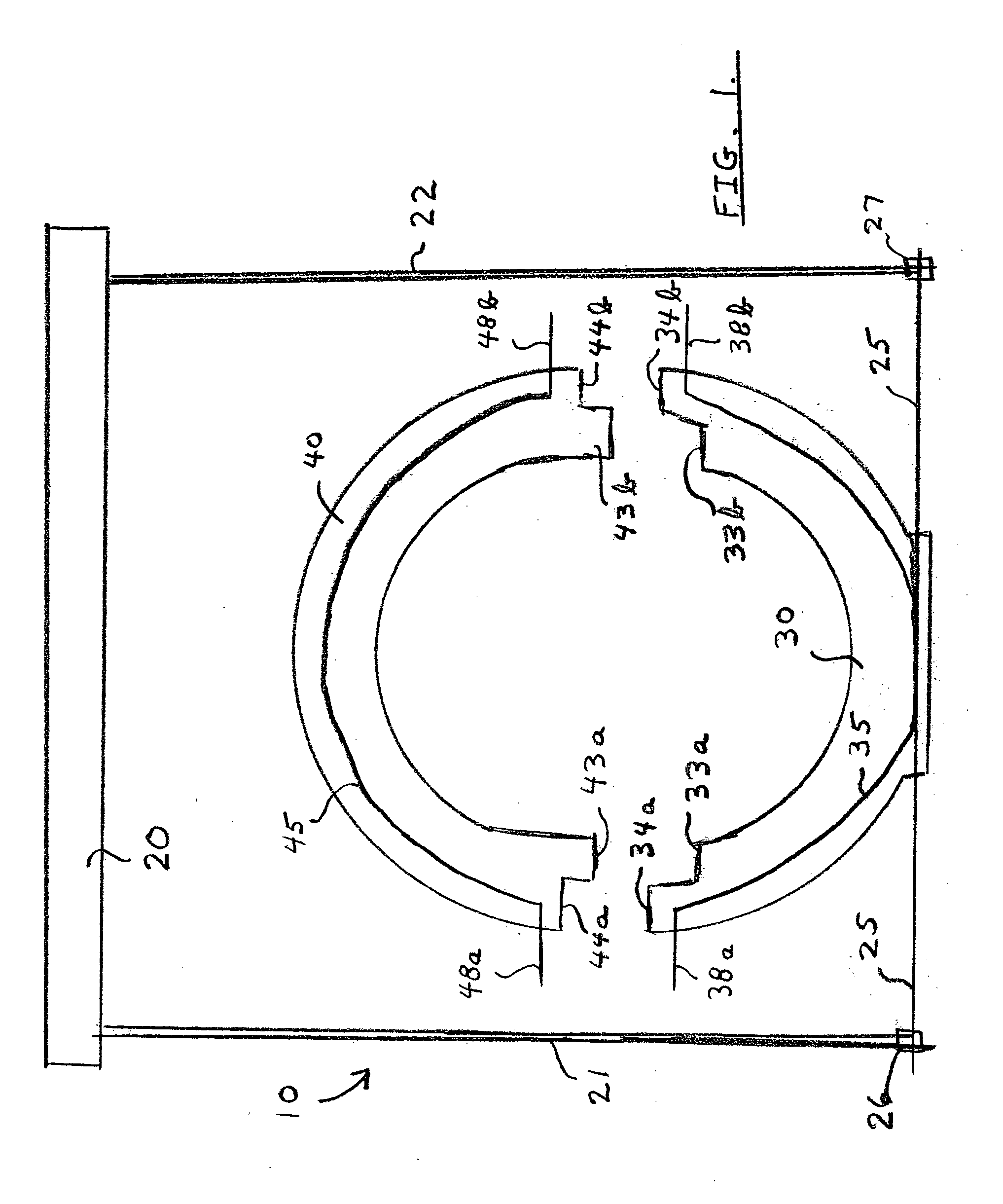
[0027] Referring to the drawing FIG. 1, the overall electrical service conduit system is indicated at numeral 10.

[0028] Numeral 20 indicates an upper solid portion of the interior of a building to be serviced.

[0029] Extending from the solid element 20 are plural rod elements 21 and 22. Rods 21 and 22 are attached to a lower plate means 25 by nut and washer units shown at 26 and 27.

[0030] The lower plate 25 is part of a lower concrete encasement 30. The concrete used in unit 30 can be, for example, a type of foam impregnated lightweight concrete.

[0031] The lower flat plate 25 has been weld-mounted to an upper curved plate 35.

[0032] Concrete encasement section 30 is precast and is generally in the shape of a half clamshell for purposes to be further described.

[0033] The lower concrete encasement section 30 has recessed area portions as indicated at numerals 33a and 33b. It further has protruding exterior portions as shown at numerals 34a and 34b.

[0034] The upper curved plate 35...


PUM


Abstract

A system and method to route electrical service conduits through the interior of a building and also to comply with the National Electrical Code(NEC). The system includes the use of a two inch concrete encasement which is reinforced by metal plates. A lower portion of the concrete encasement has a flat metal bar therein for mounting to rods extending from a secure ceiling area of a building. The protective nature of the encasement enables the service conduit to be designated as outside of a building and thus in compliance with NEC standards.

Description

BACKGROUND AND OBJECTS OF THE INVENTION [0001] The present invention is generally related to the building and electrical service conductor arts. [0002] In accordance with the National Electrical Code, hereinafter “NEC”, electrical service conductors must be positioned so as not to pass through the interior of a building. [0003] Electrical service conductors are considered to be outside of a building if they are confined by not less than two inches of brick or concrete. [0004] As shown in the Prior Art drawing of FIG. 2, a building 100 is serviced via service conductors 101 and transformer 102. [0005] When new service conductors are installed, current practice requires tearing up the concrete floor 105, installing the service conductors, and reconstructing the floor. This is clearly a very costly and time-consuming process. [0006] Accordingly, it is an object of the present invention to set forth a novel system and method to avoid the above described costly process and still be withi...

Claims


Application Information

Patent Timeline
IPC IPC(8): E04B9/00
CPCH02G3/0456H02G9/04H02G3/0481
Inventor FOX, MICHAEL C.
Owner DUCTCRETE
Why Eureka
Try Eureka