Heat Exchanger

a technology of heat exchanger and heat exchanger plate, which is applied in the direction of indirect heat exchanger, refrigeration components, lighting and heating apparatus, etc., can solve the problems of increased cost and failure of header tanks to assume an appropriate cross-sectional profile, and achieve enhanced heat exchange performance, and enhanced heat exchange performance

Inactive Publication Date: 2007-09-06
SHOWA DENKO KK
View PDF9 Cites 17 Cited by
  • Summary
  • Abstract
  • Description
  • Claims
  • Application Information

AI Technical Summary

Benefits of technology

[0028] With the heat exchanger according to pars. 7) and 8), the flow of refrigerant can be appropriately set for enhancing heat exchange performance. For example, when the heat exchanger is used as a gas cooler of a supercritical refrigeration cycle, the gas cooler exhibits enhanced heat exchange performa

Problems solved by technology

However, the header tanks fail to assume an appropriate cross-sectional profile in accordance with, for example, an installation space for the heat exchanger.
In order to provide, in various applications, appropriate cross-sectional shapes and areas of the refrigerant channel o

Method used


Image

  • Heat Exchanger
  • Heat Exchanger
  • Heat Exchanger

Examples


embodiment 1

[0059] This embodiment is shown in FIGS. 1 to 9 and is implemented by applying a heat exchanger according to the present invention to a gas cooler of a supercritical refrigeration cycle.

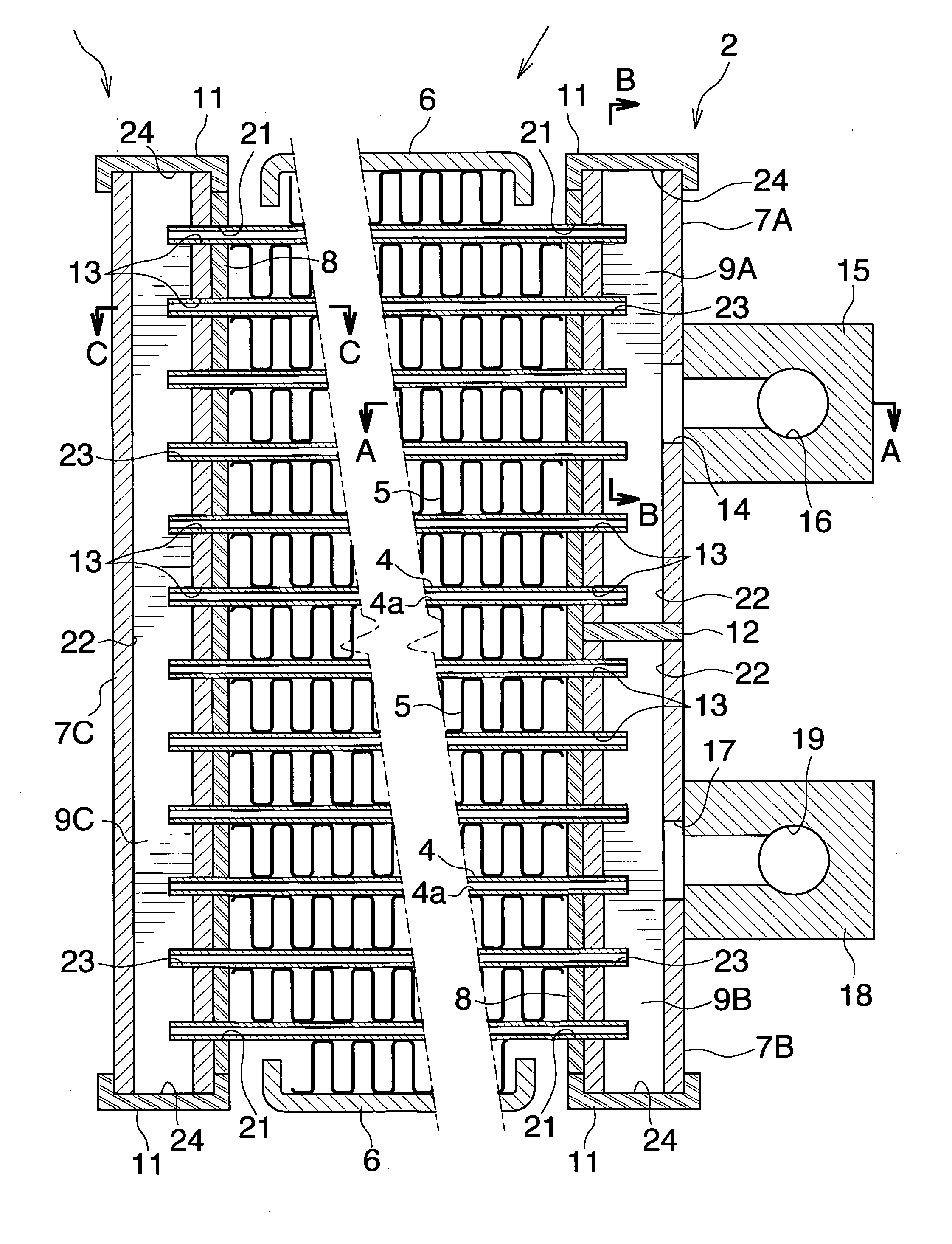
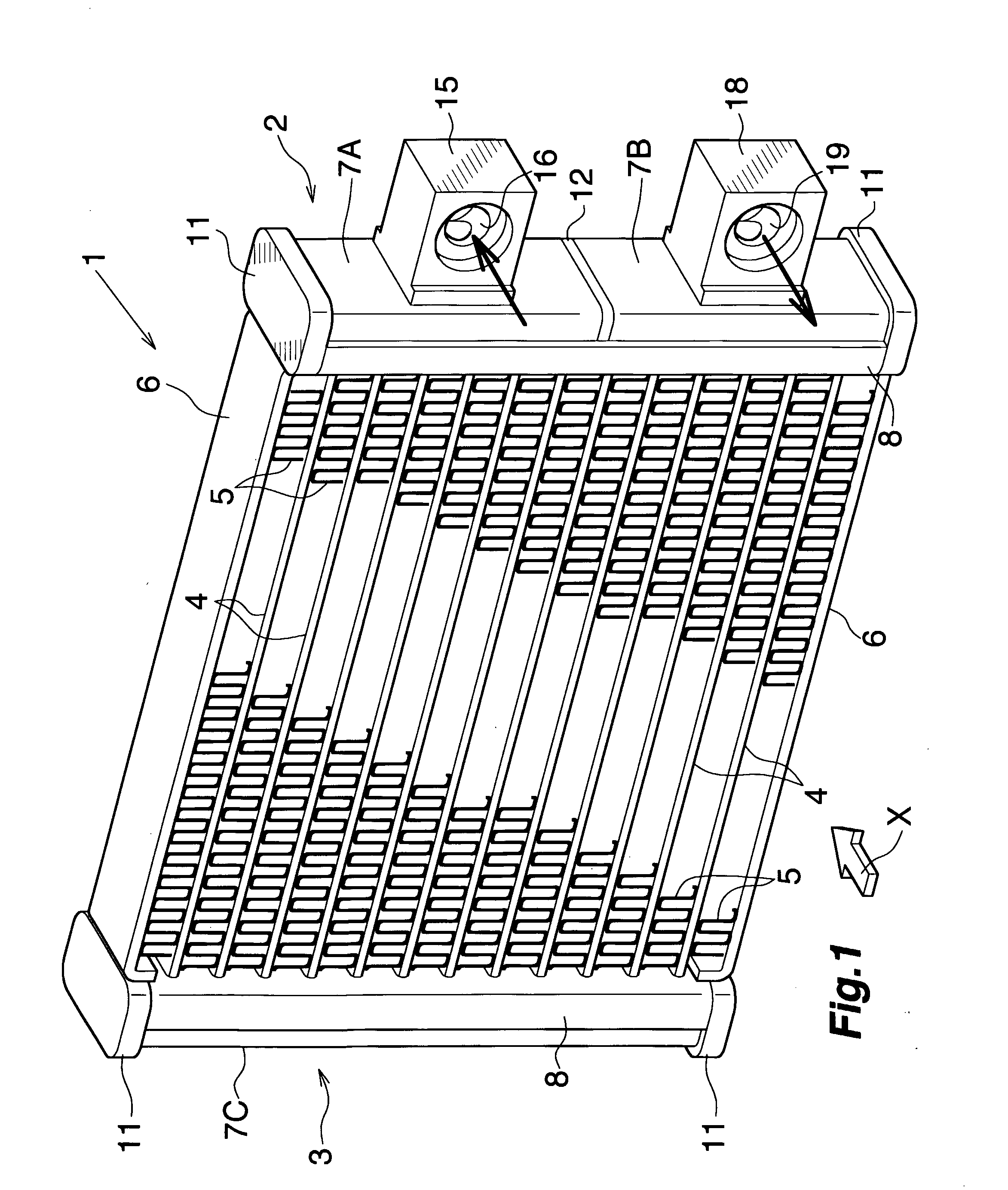
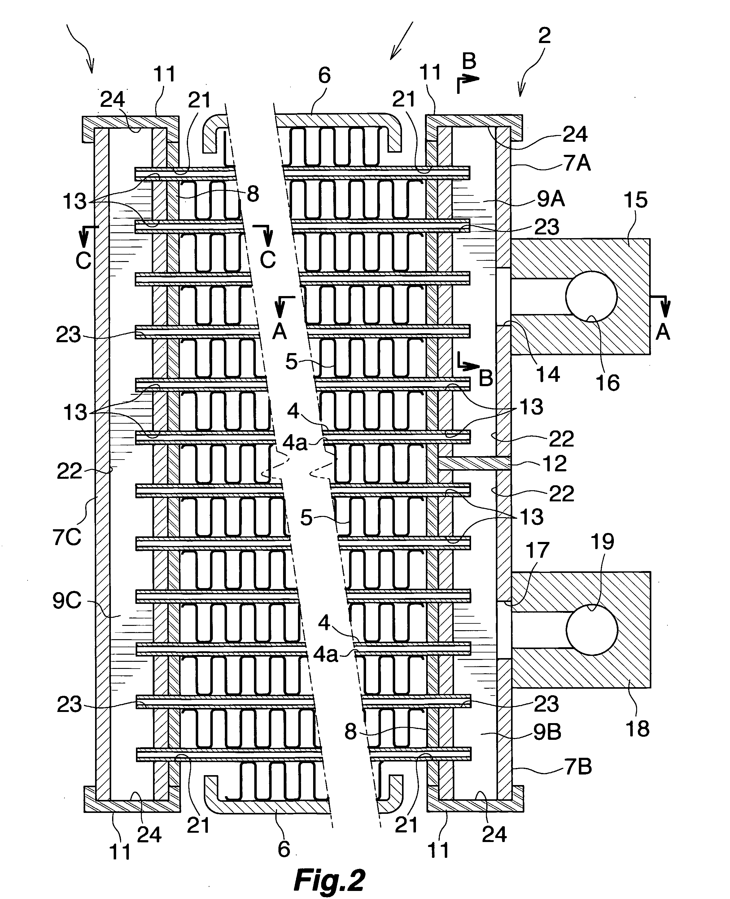
[0060] With reference to FIGS. 1 and 2, a gas cooler 1 of a supercritical refrigeration cycle wherein a supercritical refrigerant, such as CO2, is used includes two header tanks 2, 3 extending vertically and separated from each other in the left-right direction; a plurality of flat heat exchange tubes 4 arranged in parallel between the two header tanks 2, 3 and separated from one another in the vertical direction; corrugated fins 5 arranged in respective air-passing clearances between adjacent heat exchange tubes 4 and at the outside of the upper-end and lower-end heat exchange tubes 4 and each brazed to the adjacent heat exchange tubes 4 or to the upper-end or lower-end heat exchange tube 4; and side plates 6 of bare aluminum material arranged externally of and brazed to the respective upper-end an...

embodiment 2

[0079] This embodiment is shown in FIGS. 13 to 20 and is implemented by applying a heat exchanger according to the present invention to an evaporator of a supercritical refrigeration cycle.

[0080] With reference to FIGS. 13 and 15, an evaporator 40 of a supercritical refrigeration cycle wherein a supercritical refrigerant, such as CO2, is used includes two header tanks 41, 42 extending in the left-right direction and separated from each other in the vertical direction; a plurality of flat heat exchange tubes 43 arranged in parallel between the two header tanks 41, 42 and separated from one another in the left-right direction; corrugated fins 44 arranged in respective air-passing clearances between adjacent heat exchange tubes 43 and at the outside of the left-end and right-end heat exchange tubes 43 and each brazed to the adjacent heat exchange tubes 43 or to the left-end or right-end heat exchange tube 43; and side plates 45 of bare aluminum material arranged externally of and braz...


PUM


Abstract

A heat-exchanger header tank of a gas cooler includes a tank formation member, a tube-connecting plate joined to the tank formation member outer surface, and a partition disposed within and joined to the tank formation member to divide the tank formation member interior into plural refrigerant channels extending in the longitudinal direction of the tank formation member and arranged in the front-rear direction. Tube insertion holes are formed in a wall of the tank formation member and in the tube-connecting plate at mutually aligned positions. Tube-end fit cutouts partially receiving corresponding end portions of heat exchange tubes are formed on the partition to align with corresponding tube insertion holes. The cross-sectional profile of the header tank can be appropriately selected for an installation space for the gas cooler, and the cross-sectional shape and area of a refrigerant channel can be readily changed.

Description

CROSS REFERENCE TO RELATED APPLICATIONS [0001] This application is an application filed under 35 U.S.C. § 111(a) claiming the benefit pursuant to 35 U.S.C. § 119(e)(1) of the filing dates of Provisional Application Nos. 60 / 580,145 and 60 / 662,360 filed Jun. 17, 2004 and Mar. 17, 2005, respectively, pursuant to 35 U.S.C. § 111(b).TECHNICAL FIELD [0002] The present invention relates to a heat exchanger, and more particularly to a heat exchanger favorably usable as a gas cooler or an evaporator of a supercritical refrigeration cycle in which a CO2 (carbon dioxide) refrigerant or a like supercritical refrigerant is used. [0003] Herein and in the appended claims, the downstream side of flow (represented by arrow X in FIGS. 1 and 13) of air in a heat exchanger is referred to as the “front,” and the opposite side as the “rear,” and the term “aluminum” encompasses aluminum alloys in addition to pure aluminum. BACKGROUND ART [0004] A conventionally known heat exchanger for use in a supercriti...

Claims


Application Information

Patent Timeline
IPC IPC(8): F28F9/02F28D7/06F25B1/00F25B9/00F25B39/00F28D1/03F28D1/053F28F1/02F28F9/00F28F9/04
CPCF25B9/008F25B39/00F25B2309/061F28D1/0391F28D1/05391F28D2021/0073F28F2225/08F28F9/001F28F9/0207F28F9/0229F28F9/0246F28F9/0251F28F2255/16F28F1/022
Inventor ICHIYANAGI, SHIGEHARU
Owner SHOWA DENKO KK
Why Eureka
Try Eureka