Viscous fan drive having modified land design and armature venting

a fan drive and land design technology, applied in the direction of fluid couplings, clutches, couplings, etc., can solve the problems of inconsistent torque generation, difficult to get the fan drives to engage, slow response time of the fan drive, etc., to achieve the effect of increasing reducing the speed of the fan, and restricting the fluid travel of the viscous fluid

Active Publication Date: 2007-09-06
BORGWARNER INC
View PDF15 Cites 15 Cited by
  • Summary
  • Abstract
  • Description
  • Claims
  • Application Information

AI Technical Summary

Benefits of technology

[0010] The present invention addresses some of the issues described above by providing viscous fan drive system in which the radial slots do not cut across the outermost lands. Viscous fluid in the labyrinth will impact into an innermost one of at least one continuous lands located radially outwardly at the end of the radial slots of the cover and clutch as it is flung radially outwardly within the labyrinth. Since the clearance between the lands and grooves in this area of the shear space is small and the shear space is continuous, the viscous fluid travel will be restricted. As such, a continuous film develops between the adjacent surfaces of the continuous lands in the clutch and cover in the labyrinth or shear space, which in turn results in a much larger torque generation (i.e. increase in fan speed, or engagement) at a given input speed. Hence, the fan drive engages more quickly without adversely affecting disengagement performance.

Problems solved by technology

For many years, one of the problems associated with fluid-coupling devices used to drive radiator cooling fans is that these fan drives experience slow response times to engage.
However, the lower the fan speed, the more difficult it is to get the fan drives to engage.
This gives inconsistent torque generation.
Another problem with current electronically controlled viscous fan drives involves electronic control of the fluid control valve.

Method used


Image

  • Viscous fan drive having modified land design and armature venting
  • Viscous fan drive having modified land design and armature venting
  • Viscous fan drive having modified land design and armature venting

Examples


Embodiment Construction

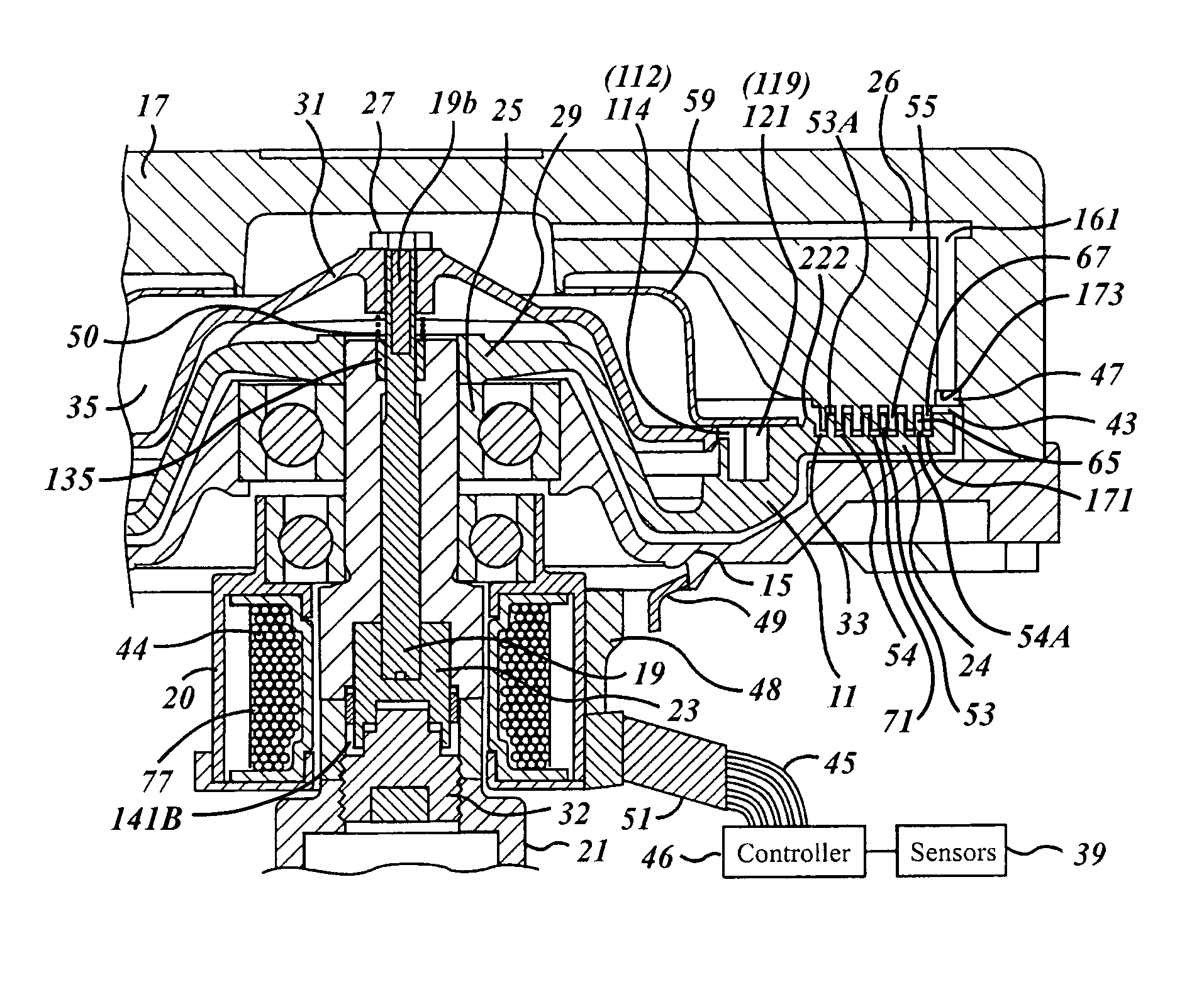
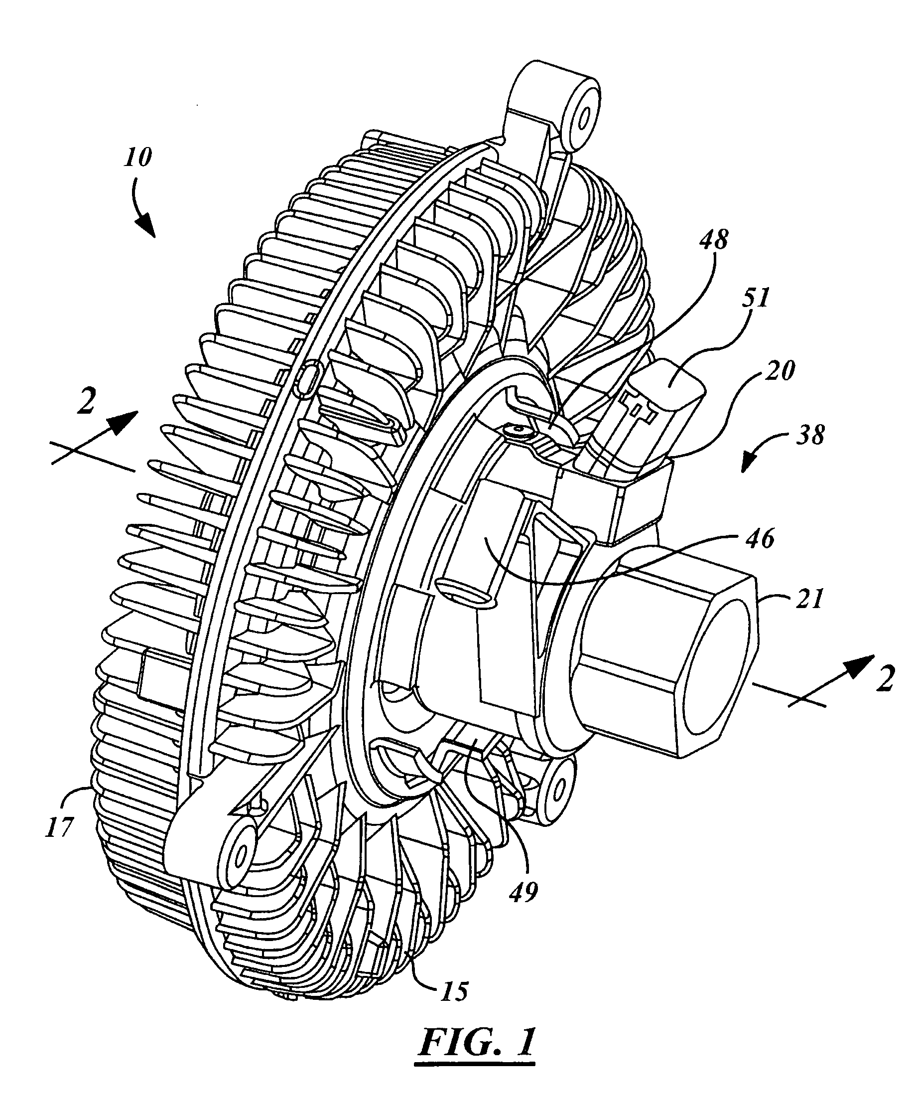
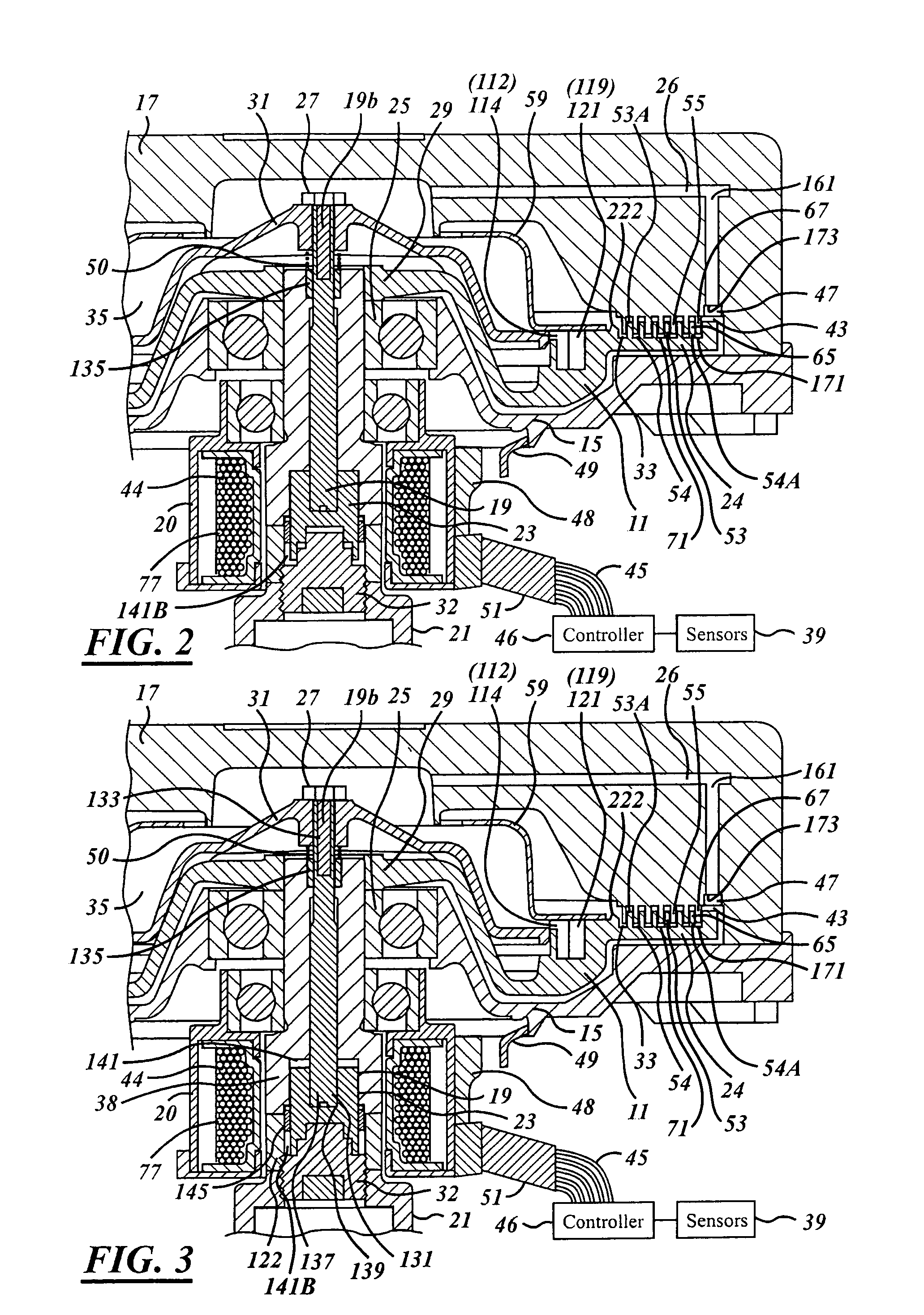
[0019] Referring now to the drawings, which are not intended to limit the invention, FIGS. 1-6 illustrates one preferred form of a fluid-coupling device 10 (“viscous fan drive”) of a type utilizing the present invention. The fluid-coupling device 10 includes an input-coupling member, or clutch, generally designated 11, and an output-coupling member, or assembly, generally designated 13. The assembly 13 includes a housing member (body) 15, and a cover member (enclosure) 17, the members 15 and 17 being secured together by a rollover of the outer periphery of the cover member 17, as is well known in the art.

[0020] The fluid-coupling device 10 is adapted to be driven by a liquid cooled engine, and in turn, drives a radiator-cooling fan, neither of which is shown herein. The fan may be attached to the housing member 15 by any suitable means, such as is generally well known in the art, and as is illustrated in the above-incorporated patents. It should be understood, however, that the use...


PUM


Abstract

A viscous fan drive in which the output drive to the fan is controlled by the movement of viscous fluid from a fluid reservoir and into the operating and working chamber of the coupling during normal operation. The input-coupling assembly and cover member are formed with a unique combination of continuous and non-continuous radially extending lands and grooves designed to distribute the viscous fluid in a continuous film throughout the shear zone so as to maximize output fan speed at a given input speed. An armature-venting feature is designed to simplify the opening and closing of the valve disk in an electronic version of the viscous fan drive depending upon the desired operating condition.

Description

CROSS REFERENCE TO RELATED APPLICATION(S) [0001] The present invention is related to U.S. Pat. No. 6,752,251, filed on Nov. 4, 2002, and to U.S. patent application No. 11 / 170,828, filed on Jun. 30, 2005, which are incorporated by reference herein.TECHNICAL FIELD [0002] The invention relates generally to fan drive systems and more specifically to a viscous fan drive having a modified land design and improved armature venting. BACKGROUND ART [0003] The present invention relates to fluid-coupling devices of the type including both a fluid operating chamber and a fluid reservoir chamber, and valving which controls the quantity of fluid in the operating chamber. The devices may be electronically or mechanically controlled. [0004] Although the present invention may be used advantageously in fluid-coupling devices having various configurations and applications, it is especially advantageous in a coupling device of the type used to drive a radiator cooling fan of an internal combustion engi...

Claims


Application Information

Patent Timeline
Patent Type & Authority Applications(United States)
IPC IPC(8): F16D35/02F16D31/00
CPCF16D35/024
Inventor LIGHT, GERARD M.
Owner BORGWARNER INC
Why Eureka
Try Eureka