
Water conductivity monitoring circuit for use with a steam generator

a technology of water conductivity and steam generator, applied in the direction of separation process, membrane, treatment water, etc., can solve the problems of affecting performance, affecting the purity of water, and affecting the usefulness of the device,

Active Publication Date: 2007-09-06
WHIRLPOOL CORP
View PDF7 Cites 12 Cited by
  • Summary
  • Abstract
  • Description
  • Claims
  • Application Information

AI Technical Summary

Benefits of technology

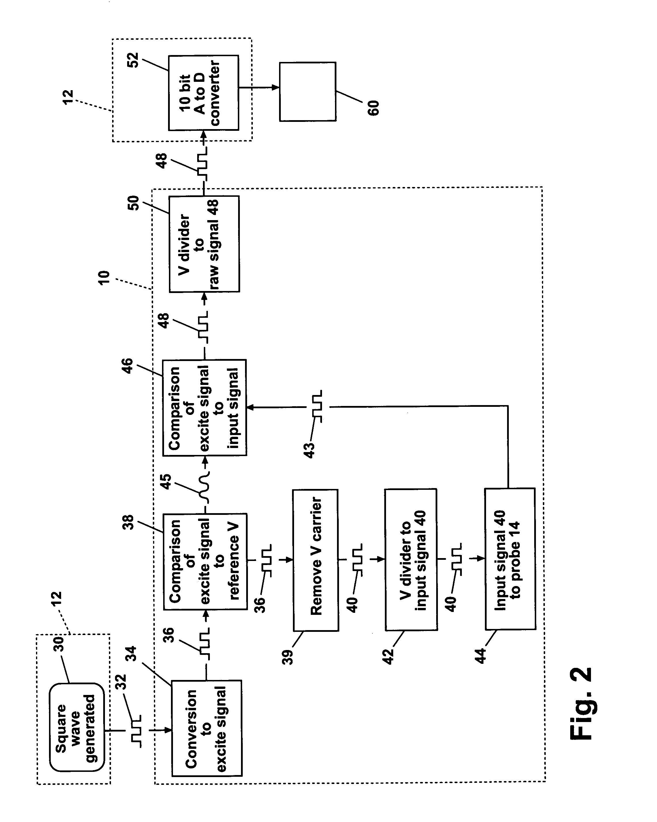
The present invention is a water conductivity monitoring circuit for a steam generator that can determine the status of a water filter upstream from the steam generator. The circuit includes a microprocessor, a probe, and a conductivity sensor circuit. The microprocessor generates a reference signal, the probe measures the conductivity of the water, and the conductivity sensor circuit sends the output signal to the microprocessor. The microprocessor compares the reference signal to the output signal to determine the value, which is then compared to a predetermined threshold level to determine the status of the filter. The circuit can also include a display to show the status of the filter visually. The technical effect of this invention is to provide a convenient and efficient way to monitor the status of the water filter in a steam generator system.

Problems solved by technology

Most common sources of water leave calcium and magnesium deposits in the boiler after the water is vaporized into steam, a cumulative build up of which adversely affects performance.
The principal problem with a filter, however, is that it must be replaced periodically when it becomes saturated with solids or when it otherwise breaks down and its usefulness expires.
But, assessing the purity of water by measuring conductivity carries its own set of problems.
As well, probes get contaminated with deposits that affect their sensitivity.
Further, known water purity conductivity devices provide only a “thumbs up” or thumbs down” assessment, measured against a fixed threshold.

Method used


Image

  • Water conductivity monitoring circuit for use with a steam generator
  • Water conductivity monitoring circuit for use with a steam generator
  • Water conductivity monitoring circuit for use with a steam generator

Examples


Embodiment Construction

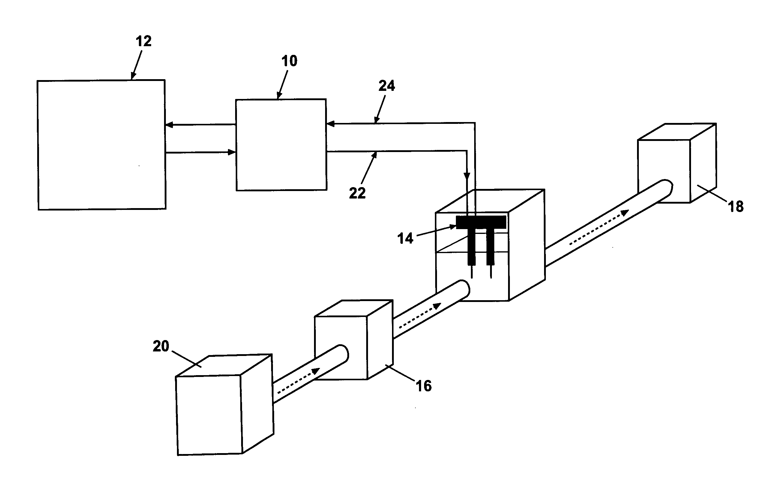
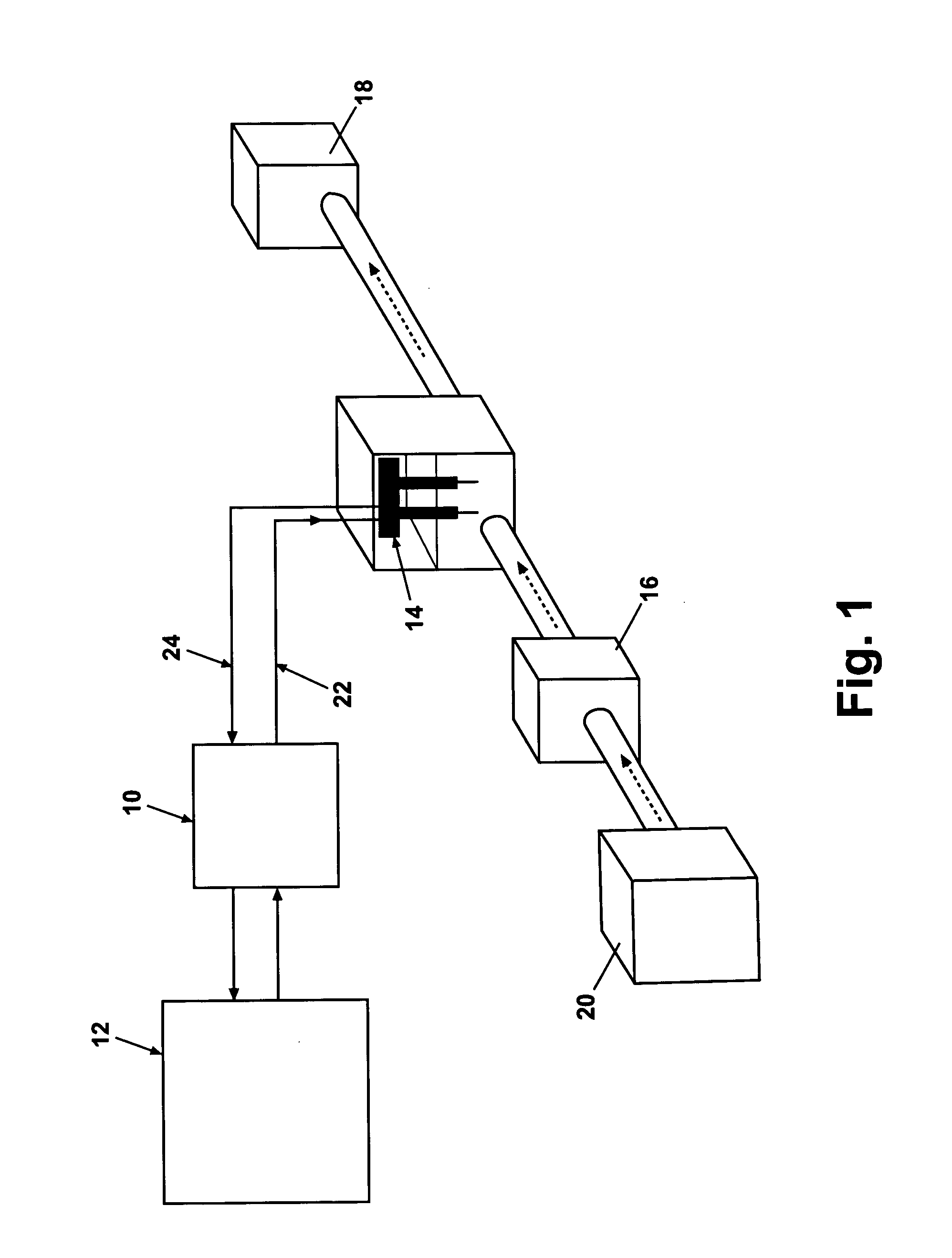
[0027] Looking first at FIG. 1, a water monitoring circuit according to the invention utilizes a conductivity sensor circuit 10 in conjunction with a microprocessor 12 to evaluate signals sent through a probe 14 positioned in water flow downstream from an water filter 16, and upstream from a steam generator 18 in a home appliance. For this embodiment, the home appliance is considered to be an oven and the water filter is an ion exchange filter. Water from a water source 20 flows through the ion exchange water filter 16, past the probe 14, to the steam generator 18 where steam is produced and introduced into the oven in a manner well-known in the art. The particular type of steam generator and filter used is not important to invention. Generally, the microprocessor 12, preferably in an electronic oven control, generates a reference or input signal that goes into the conductivity sensor circuit 10 and then to the probe 14. The input signal is modified by the water at the probe and the...


PUM

PropertyMeasurementUnit
conductivityaaaaaaaaaa
voltageaaaaaaaaaa

Abstract

A water conductivity monitoring circuit determines the status of an ion exchange filter in the water flow to a steam generator. A microprocessor sends a reference signal to a conductivity sensor circuit that converts it to an excite signal that is sent to a probe in the water flow. Any conductivity of the water alters the excite signal, and the modified signal is compared to the reference signal to establish a value indicative of the conductivity of the water. The microprocessor compares the value to at least two thresholds representative of the status of the filter.

Description

BACKGROUND OF THE INVENTION [0001] 1. Field of the Invention [0002] The invention relates generally to water conductivity monitoring circuits and, more particularly, to a circuit that uses a microprocessor for monitoring water conductivity in a steam generator. [0003] 2. Description of the Related Art [0004] Steam generation is found in home appliances for a variety of different uses. For example, it is known to use a steam generator in an oven for cooking applications. In a steam generator, a water source typically supplies water to a boiler to generate steam. For a steam generator in an oven, water can be supplied from a reservoir and pumped into the boiler, or directly from a continuously pressurized water source such as a municipal water supply. [0005] Most common sources of water leave calcium and magnesium deposits in the boiler after the water is vaporized into steam, a cumulative build up of which adversely affects performance. One solution to the build up of deposits in a b...

Claims


Application Information

Patent Timeline
Patent Type & Authority Applications(United States)
IPC IPC(8): B01D35/143
CPCB01D61/22B01D65/10B01D2313/243C02F1/008G01N27/06C02F2103/023C02F2209/05C02F2303/16C02F1/42G01N27/02G01N27/00
Inventor SAVAGE, JASON RANDALLMOORE, DWAIN FRANCISROBINSON, THOMAS N.SELLS, JOEL MATTHEW
Owner WHIRLPOOL CORP
Learn More