[0005] It is an object of the present invention to provide a carrying arrangement of the aforementioned kind that avoids impairment of the operator during operation of the power tool.
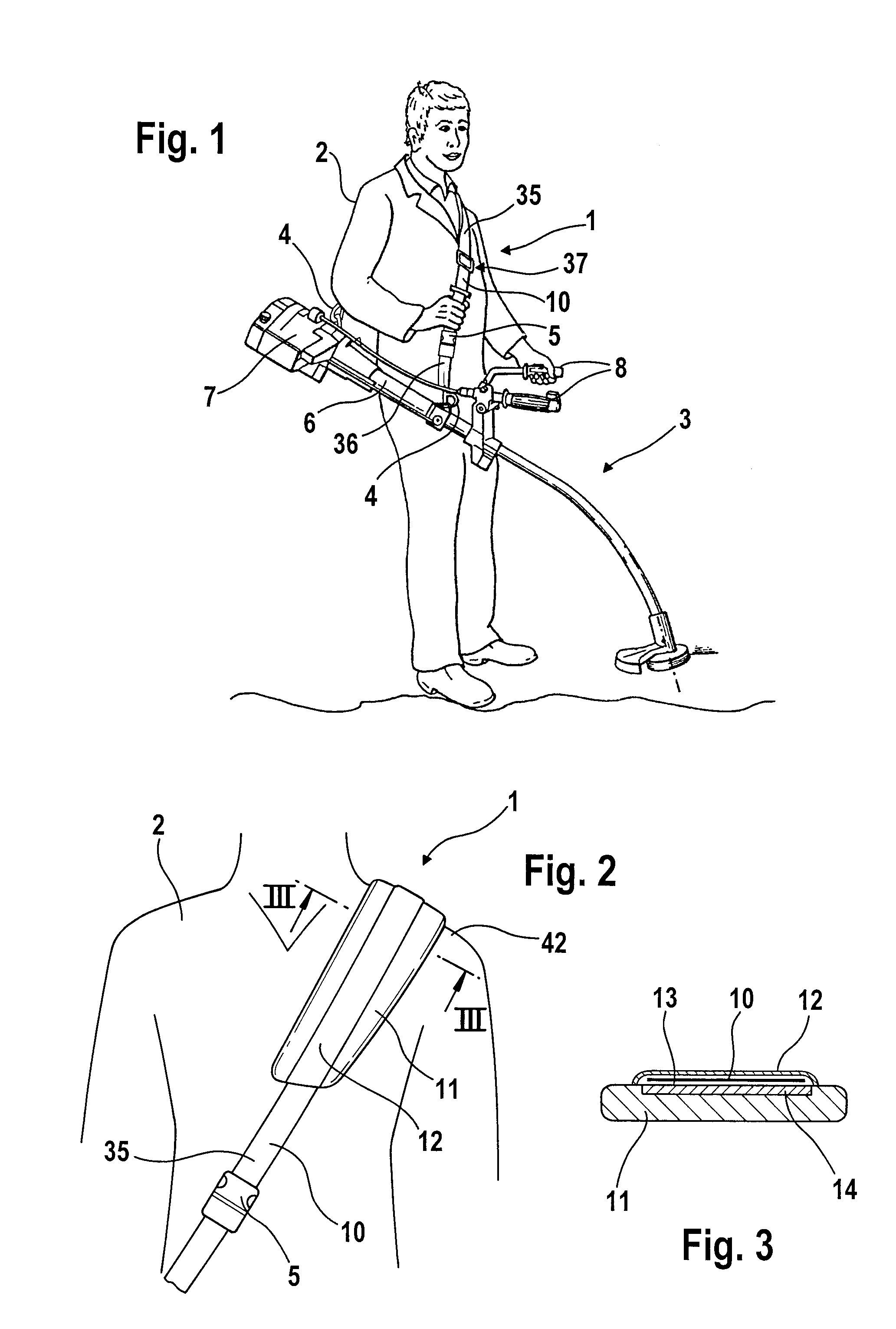
[0006] In order to prevent that the operator must move the shoulder support on his shoulder during operation of the power tool, it is provided that the carrying arrangement has means for reducing the friction between the carrying element and the shoulder support. By reducing friction, it is possible for the carrying element to slide in operation and under load in the longitudinal direction of the shoulder support. Pivoting of the powertool thus only has the effect of changing the position of the carrying element relative to the shoulder support. The shoulder support can stay in place on the shoulder of the operator. This enables unimpaired working.
[0007] Advantageously, a slideway is provided on the shoulder support for reducing the friction. In particular, the slideway is embodied on a flexible sliding plate on which the carrying element will rest in operation. By designing the sliding plate to be flexible, the sliding plate will conform easily to the
body shape of the operator. In this way, an ergonomically designed carrying arrangement is enabled. Advantageously, the sliding plate is made from plastic material. A sliding plate of plastic material can be produced in a simple way and can be connected to the shoulder support, for example, by being sewn on. Relative to conventional materials of carrying elements such as straps, cables or the like, plastic material has a minimal
coefficient of friction so that the carrying element can be moved with minimal force expenditure within the shoulder support when the power tool is connected to the carrying element.
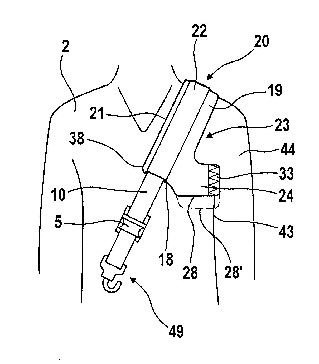
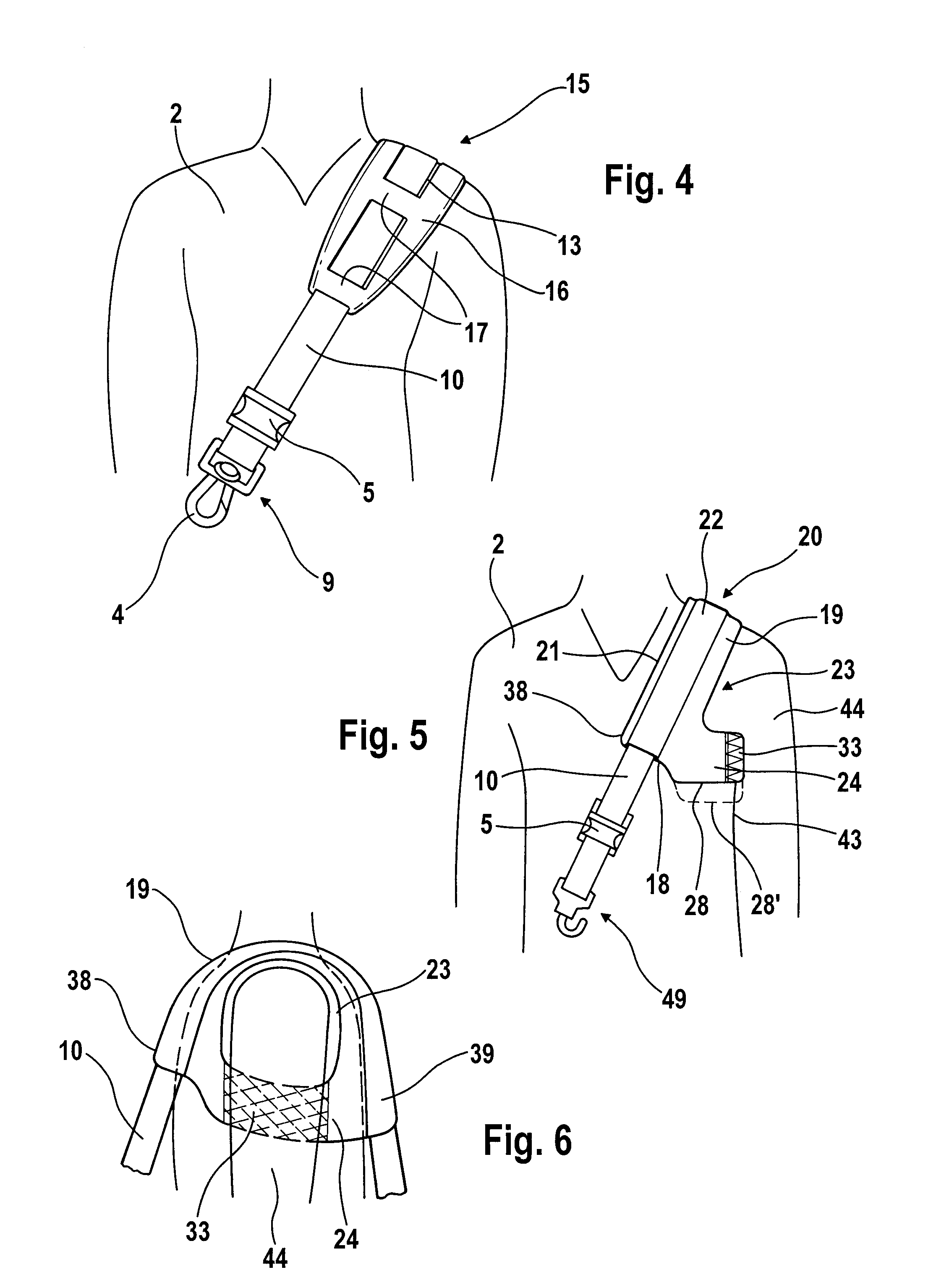
[0008] In order to be able to receive the lateral forces occurring in operation of the power tool in an excellent and ergonomic way, it is provided that the shoulder support has a shoulder section and a lateral support section that is connected to the shoulder section. On the shoulder section the carrying element is arranged and the lateral support section is designed for resting against a side of the operator. The shoulder section thus receives the forces acting vertically on the operator while the support section receives the horizontal forces at the side of the operator. In this way, it is prevented that the carrying element can move in the direction toward the neck of the operator and thereby impair or hinder the operator. Because the lateral support section according to the invention is directly connected to the shoulder section, a simple configuration is provided. Existing carrying arrangements can also be provided with a support section by simply exchanging the shoulder support. Advantageously, the lateral support section is comprised at least partially of a mesh material. Mesh material is very expandable so that an adjustment to the size of the operator can be realized. Moreover, the mesh material is thin and air-permeable so that a high carrying comfort is provided.
[0009] Advantageously, the lateral support section and the shoulder section are connected to one another in an area of the shoulder section that is to be positioned on the chest part of the operator and in an area of the shoulder section that is to be positioned on the back of the operator so that an arm opening for the arm of the operator is formed. In this way, the shoulder support can be put on like half a
vest by the operator in that the operator pushes his arm through the arm opening. The shoulder support is secured in this way in the horizontal direction and the vertical direction on the operator so that slipping or sliding is prevented. A positional fixation by additional straps, for example, a hip strap or the like, is therefore not required. Advantageously, the lower edge of the lateral support section is displaced relative to the lower edge of the shoulder section in the direction toward the free end of the carrying element. In this way, a large arm opening with comparatively minimal length of the shoulder section can be realized. In carrying arrangements with an adjusting device for adjusting the length of the carrying element, the maximum adjustment travel can be enlarged by means of the displacement between the lower edges of the shoulder section and the support section.
[0010] Expediently, the shoulder support has at least one loop through which the carrying element can be passed. However, it can also be provided that the shoulder support has a passage through which the carrying element can be guided. The passage is in particular embodied as a tube. Expediently, the carrying element has at its free ends a fastening element, respectively, for fixation of the carrying element on the power tool. In order to be able to put on the carrying element in a simple way, it is provided that the carrying element has a first section on which the shoulder support is secured and a second section; the first section and the second section of the carrying element are connected to one another by a releasable buckle. The operator can secure the two sections on the power tool, while the power tool is still resting on the ground. In order to put on the carrying element, the operator will
squat and place the first section of the carrying element across his shoulder. By closing the buckle that is arranged expediently on the chest part of the operator, the two sections are connected to one another and the carrying arrangement is now put on. The carrying arrangement has advantageously an adjusting device for adjusting the length of the carrying element. In this way, a simple adjustment of the carrying element to the
body height of the operator is possible. Advantageously, the shoulder support is embodied as a shoulder pad. In this way, the forces that are produced during operation of the power tool can be introduced excellently into the shoulder of the operator.


