Counter Sprocket Installation And Removal Tool

a technology of installation and removal tool, which is applied in the direction of screwdrivers, wrenches, manufacturing tools, etc., can solve the problems of requiring much more torque to remove the nut or bolt from the output shaft, excessive side load on the motor housing and output shaft, and damage to the transmission gear, etc., to achieve convenient removal, eliminate potential damage during the operation, and simplify the operation of installation

Inactive Publication Date: 2012-12-27
STRUB KENNETH MARTIN
View PDF7 Cites 0 Cited by
  • Summary
  • Abstract
  • Description
  • Claims
  • Application Information

AI Technical Summary

Benefits of technology

[0003]The present invention is targeted at simplifying the operation of installation and removal of the counter sprocket fastener on a motorcycle. It specifically is a device to prevent rotation of the counter sprocket thereby preventing rotation of the output shaft to facilitate removal of the bolt or nut securing the counter sprocket to the output shaft. The device is intended to hold the counter sprocket from rotation during installation

Problems solved by technology

Over time there may be corrosion or other factors, which may require much more torque to remove the nut or bolt from the output shaft.
This method can damage the transmission gears.
An al

Method used


Image

  • Counter Sprocket Installation And Removal Tool
  • Counter Sprocket Installation And Removal Tool

Examples


Embodiment Construction

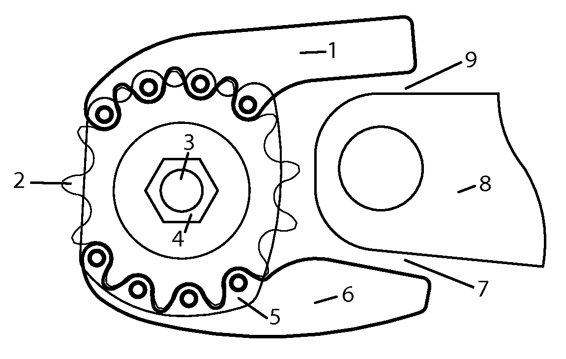
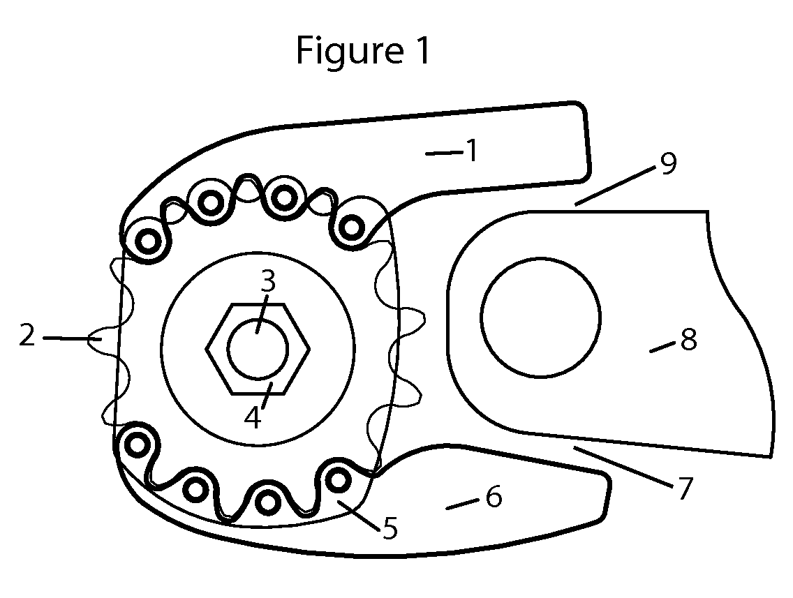
[0005]Referring to FIG. 1, a motorcycle has an output shaft 3 from the motor. A counter sprocket 2 is mounted to the output shaft 3 with a fastener 4. The fastener 4 is typically a threaded nut or bolt. The counter sprocket removal tool, consisting of three parts in this embodiment, the faceplate 5 connected to the 2 engagement arms 1 and 6. Depending on installation or removal, the force is either clockwise or counter-clockwise. During installation, the fastener 4 would need to be rotated clockwise about the output shaft 3. The engagement arms 1,6 are meshed with the teeth of the sprocket 2. When the output shaft 3 tries to rotate, the counter sprocket 2 which has a mating spline pattern, must rotate with the output shaft 3. The counter sprocket tool as depicted in FIG. 1 shows the engagement arms 1,6 interlocked in the counter sprocket 2. This engagement would require the counter sprocket tool to rotate with the counter sprocket 2. The upper engagement arm 1 will come to a stop po...


PUM

PropertyMeasurementUnit
Forceaaaaaaaaaa
Sizeaaaaaaaaaa

Abstract

A counter sprocket rotational movement limiting device for installing and removing the fasteners of counter sprockets on motorcycles, comprising of a profile which will engage the teeth of the sprocket and a protruding arm or set of arms configured to come to rest on the top and or bottom of the swingarm, limiting the rotational movement of the counter sprocket.

Description

FIELD OF THE INVENTION[0001]The invention relates to a mechanical device capable of holding a counter sprocket from rotating during installation and removal of the fastening device typically a bolt or nut, while not creating an undue side load on the output shaft or transferring an unnecessary impact to the drive train.BACKGROUND OF THE INVENTION[0002]A counter sprocket is secured to a splined output shaft on the motor of chain drive motorcycles. The counter sprocket is typically secured with a bolt or nut, to the output shaft. This bolt or nut has specific torque specifications to achieve maximum effectiveness. The output shaft is designed to be as close as possible to the pivot point of the swingarm to minimize the distance change of the sprockets during articulation of the swingarm. Over time there may be corrosion or other factors, which may require much more torque to remove the nut or bolt from the output shaft. Past procedures include putting the transmission in gear to creat...

Claims


Application Information

Patent Timeline
IPC IPC(8): B25B27/14
CPCB25B13/48Y10T29/53991B25B23/0085
Inventor STRUB, KENNETH MARTIN
Owner STRUB KENNETH MARTIN
Why Eureka
Try Eureka