Rotary electrical machine

Active Publication Date: 2018-03-15
MITSUBISHI ELECTRIC CORP
View PDF0 Cites 0 Cited by
  • Summary
  • Abstract
  • Description
  • Claims
  • Application Information

AI Technical Summary

Benefits of technology

The present invention helps in determining the positions where multiple core pieces are connected to form an armature core by taking into consideration the magnetomotive forces generated by the coils wound around the magnetic pole teeth. This results in a rotary electrical machine that can prevent distortion in the armature core and improve its operation. Compared to conventional instances, this invention helps in achieving better performance even when multiple core pieces are used to form the armature core.

Problems solved by technology

However, a problem of distortion in the armature core arises on account of the heat input into the armature core caused by welding.
In other words, distortion in the armature core caused by wielding is an underlying factor of impairment of the operation characteristics of the rotary electrical machine.

Method used


Image

  • Rotary electrical machine
  • Rotary electrical machine
  • Rotary electrical machine

Examples


embodiment 1

[0044

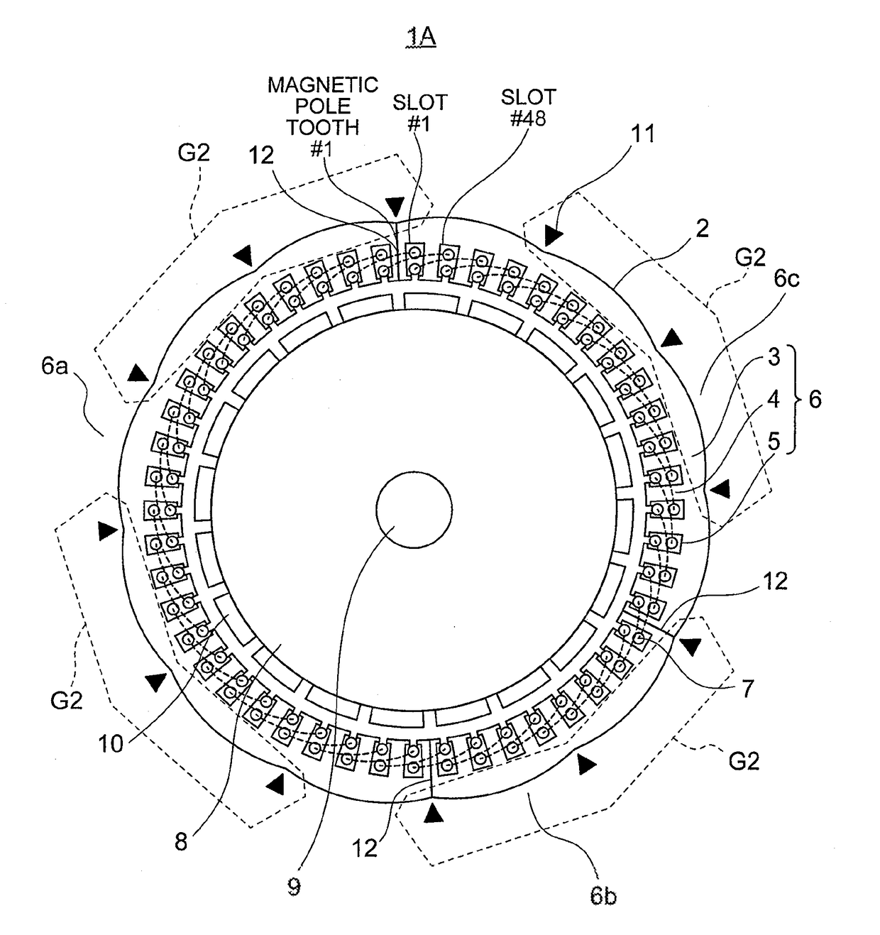
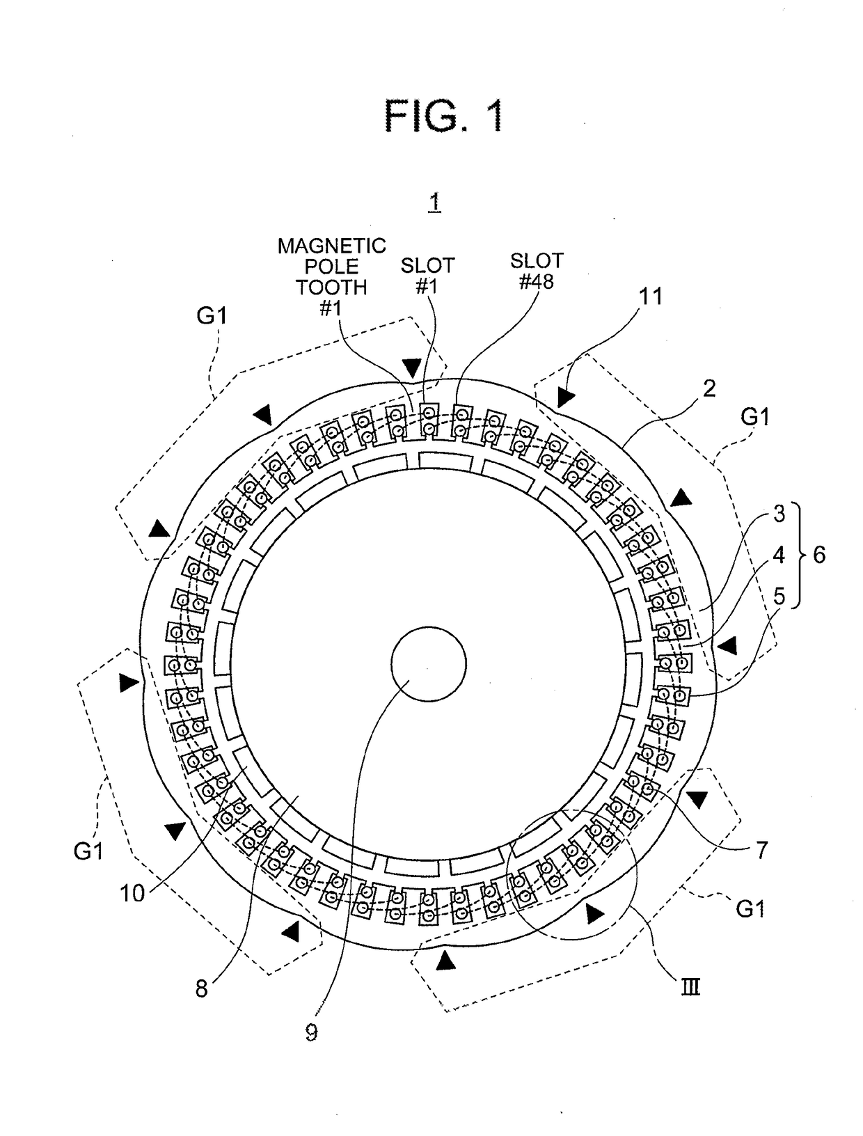
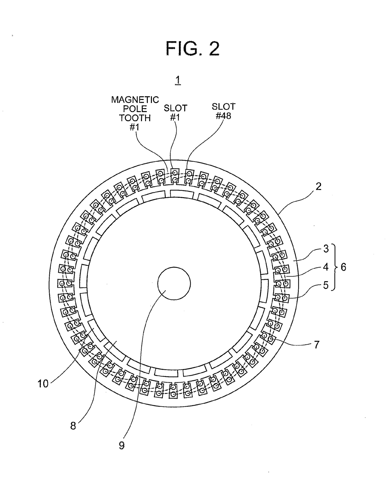
[0045]FIG. 1 is a plan-view diagram illustrating a rotary electrical machine 1 of Embodiment 1 of the present invention. FIG. 2 is a plan-view diagram illustrating the rotary electrical machine 1 of FIG. 1 without depicting the connection positions 11 or distortion of an armature core 6 caused by welding. FIG. 3 is an enlarged perspective-view diagram illustrating portion III of FIG. 1.

[0046]In the present Embodiment 1 an instance is illustrated wherein the number of slots 5 of an armature 2 (hereafter referred to as number of slots Q) is 48 and the number of magnets 10 of a rotor 8 (hereafter referred to as number of magnetic poles P) is 20. In FIG. 1 and FIG. 2 dotted lines represent the coil end portions at which coil sides of coils 7 disposed in respective slots 5 are linked to each other. In FIG. 3 the coils 7 of FIG. 1 have been omitted.

[0047]The rotary electrical machine 1 is provided with the armature 2 and the rotor 8. The armature 2 has the armature core 6 having an a...

case 1

[0066

[0067]Case Where P / gcd(Q, P)=6a+1

[0068]In this case, the electrical angles of the three magnetic pole teeth #[x+Q / {gcd(Q, P)×m}×b] are 0°, 60° (240°) and 120°, respectively. Numerical values in brackets (i.e. 240°) represent electrical angles for coils 7 disposed in reverse winding.

case 2

[0069

[0070]Case Where P / gcd(Q, P)=6a+2

[0071]In this case, the electrical angles of the three magnetic pole teeth #[x+Q / {gcd(Q, P)×m}×b] are 0°, 120°, 240°, respectively.


PUM


Abstract

This invention, is concerning a rotary electrical machine, wherein, where Q is the number of a plurality of slots, P is the number of a plurality of magnets, gcd(Q, P) is the greatest common divisor of Q and P, m is the number of phases, and one position group is defined as a set of m positions spaced from each other along the circumferential direction of the armature core by a pitch of an angle of [360 / {gcd(Q, p)×m}]°, an armature core is: formed by connection of a plurality of core pieces at connection positions that are set to positions included in one or more respective position groups from among gcd(Q, P) position groups formed at equal pitch along the circumferential direction of the armature core.

Description

TECHNICAL FIELD[0001]The present invention relates to a rotary electrical machine that is provided with an armature and a rotary.BACKGROUND ART[0002]In conventional rotating electric machines, armature cores are formed using a laminated core, being a stack of thin plate-like steel sheets, in order to suppress generation of heat due to eddy current, logs in the armature. Armature cores are often formed using split cores, in order to enhance the production workability of the armature. In such cases, welding is resorted to as an ordinary method for connecting to each other the steel sheets of the laminated core, and to connect to each other the split cores (see for instance PTL 1 and 2).[0003]Welding is a method that relies on a simple operation and that allows obtaining high connection strength easily and reliably. However, a problem of distortion in the armature core arises on account of the heat input into the armature core caused by welding.[0004]The greater the overall uniformity ...

Claims


Application Information

Patent Timeline
IPC IPC(8): H02K1/18H02K1/27H02K1/16H02K3/28
CPCH02K1/185H02K1/278H02K1/16H02K3/28H02K15/024H02K2213/03
Inventor UMEDA, TAKASHIKIMURA, YASUKIHASHIMOTO, AKIRA
Owner MITSUBISHI ELECTRIC CORP
Why Eureka
Try Eureka